
Leak Sensor

a leakage sensor and sensor technology, applied in the field of leakage sensors, can solve the problems of embarrassing leakage for stoma patients, high inconvenience of leakage, wound care patients can have problems with leakage from dressings, etc., to achieve less sensitive, enhance measurement accuracy, and increase skin conductivity

Active Publication Date: 2010-02-04
COLOPLAST AS
View PDF7 Cites 172 Cited by
  • Summary
  • Abstract
  • Description
  • Claims
  • Application Information

AI Technical Summary

Benefits of technology

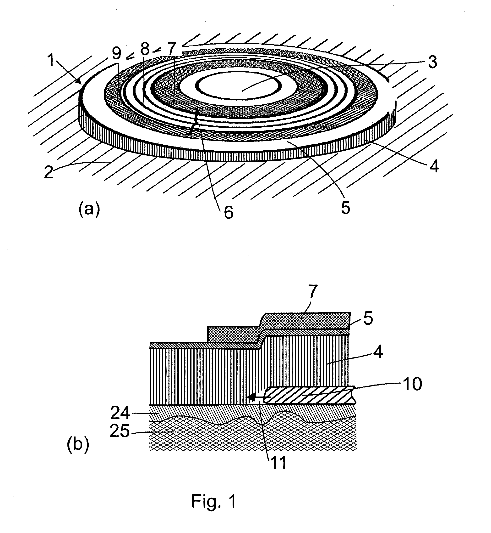
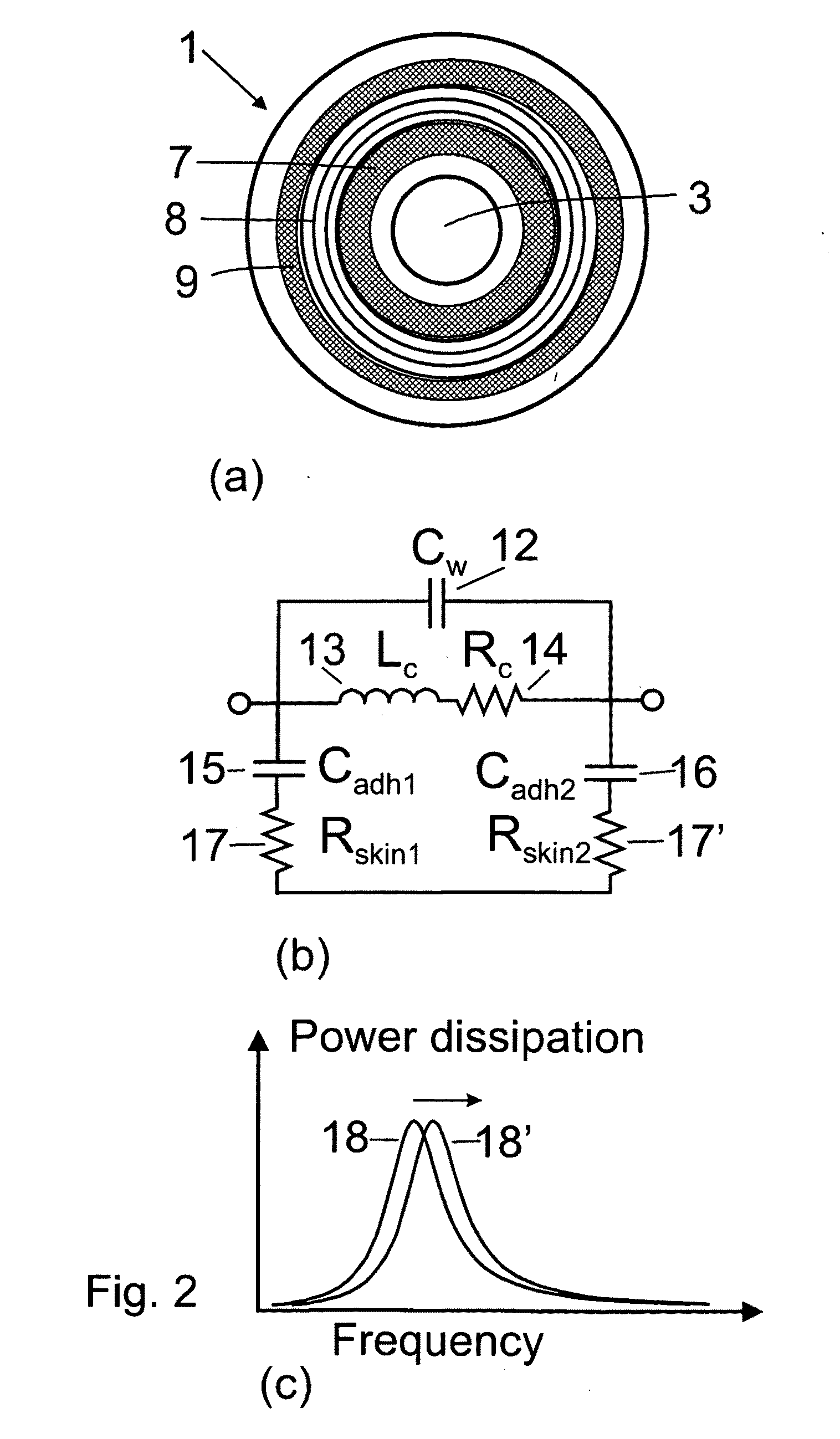
[0085]where εadh is the relative effective dielectric constant of the adhesive, the foil and the top non-conductive layer of the skin, ε0 is the vacuum permittivity, Aring is the area of the ring capacitor and ladh is the distance between the electrically conductive films and the conductive part of the skin. When a leak occurs e.g. from the centre of the bandage and outwards, the distance ladh, between the top conductive films of the inner ring 7 and the conductive layer of the skin 25 increases, as shown in FIG. 1b. As a result, Cadh1 decreases, and according to Eqn. 1, fres increases. The present invention is therefore capable of detecting parts of the adhesive coming off the skin and voids or channels created before leakage of body fluid or faeces. Another advantage of the present invention is that enables detection of both leakages originating from the peripheral of the bandage and propagating towards the opening 3 and leakages originating from the opening 3 and towards the periphery.
[0086]On the other hand, the adhesive also absorbs water. The effective dielectric constant of the adhesive / foil is approximately εadh˜2.5, whilst the dielectric constant of water is as much as ˜80 at DC, and somewhat smaller at higher frequencies. Therefore, as the adhesive absorbs water, according to Eqn. 2, Cadh1 increases, and according to Eqn. 1, fres decreases. As a consequence of this behaviour, by monitoring the resonance frequency as a function of time, a leakage can be discriminated against other changes induced by the environment, such as changes in temperature, a soaked adhesive due to sweat, mechanical stresses or other non-leakage induced sensor signals by analysing the temporal evolution of the resonance frequency.
[0087]The dimensions of the bandage illustrated in FIG. 1 may for a wound dressing be in the range of diameters or lengths from 5 mm to 500 mm, more preferably from 30 mm to 150 mm. For an ostomy bandage, the diameters or lengths may be in the range from 30 mm to 300 mm and more preferably from 50 mm to 150 mm. The periphery of the bandage may have various geometric forms such as circular, elliptical, rectangular, polygonal, or other forms. The electrically conductive pattern comprising coils and / or capacitor electrodes are not exclusively confined to spirals for the coils and circles for the capacitor electrodes as illustrated in the drawings. The coils may form any pattern of conductive leads with mutual electromagnetic coupling and any area of a conductive film with a closed or almost closed loop surrounding a stoma or a wound may form the electrode on a foil or an adhesive. Electrically conductive patterns also include patterns where the capacitor electrodes and the inductors are spatially distributed for example by means of a planar coil with a sufficiently broad wire width forming an electrode which achieves an appropriate capacitance to the conductive layer of the skin of a mammal. Appropriate capacitances mean that the resonance frequency according to Eqn. 1 matches suitable frequency bands for a reader unit and that it is not dominated by parasitic capacitances. The values of the capacitances and the inductances should thus match the frequency band chosen. For example, a typical value of the inductance is 10 μH, and a typical value of the combination of Cadh1 and Cadh2 is 20 pF yielding a resonance frequency of fres=11 MHz according to Eqn. 1.
[0088]According to the present invention, the electrically conductive pattern surrounds the stoma or the wound and it can be designed in various sizes and shapes depending on the size and the shape of the stoma or wound. For a certain resonance frequency within a certain frequency band of the reader circuit, the dimensions of the electrically conductive pattern needs to be adapted to the frequency band. There are a number of parameters to tune in order to match a certain resonance frequency. The main parameters are the thickness of the adhesive (ladh in Eqn. 2), the area of the ring-capacitance electrode (Aring in Eqn. 2) and the number of wire turns (n) for the inductance, since in Eqn. 1 Lc ∝:n.
[0089]The conductivity of skin increases several orders of magnitude when the frequency changes from DC up to approximately 100 MHz and the difference between wet skin and dry skin becomes smaller, the higher the frequency (see e.g. V. Raicu et al. Phys. Med. Biol. 45 (2000) L1-L4). Lower frequencies may be preferred for immunity to parasitic effects and the ability to penetrate intervening material. Higher frequencies enhance measurement accuracy and make the sensor less sensitive to variations in skin humidity.
[0090]Standardized and suitable frequency bands for passive radio-frequency-identification-tags are for

Problems solved by technology

Some stoma patients experience problems with leakage from ostomy bags or leakage of body fluids from the ostomy.
A leakage for a stoma patient can be embarrassing and highly inconvenient.
Also wound care patients can have problems with leakages from a dressing.
It is therefore not suitable to detect a leak before it has wetted the medium.
This method is therefore not suitable for detecting a leak at the interface between the skin and an adhesive, because this interface cannot in a practical way be placed between two measuring electrodes.
It is therefore not suitable for detecting a leak due to exudates of a wound or discharge from a stoma propagating between the skin and an adhesive to the periphery of a bandage or dressing.
However, such a device measuring the conductivity of the adhesive only makes a respond in the case, where the adhesive has lost its effectiveness and it is desirable to change the adhesive.
Furthermore, as the device measures directly between the two series of electrodes, the device will not detect a leak occurring as a consequence of a skin-fold, a scar or a wet spot creating a channel for a leak and where a leak propagates between the skin and the adhesive.

Method used


Image

  • Leak Sensor
  • Leak Sensor
  • Leak Sensor

Examples


example 1

[0125]In example 1 the sensor response of a leak sensor for an adhesive of an ostomy bag with the adhesive attached to the skin of a person is determined when a leak is occurs. The leak sensor comprises an electrically conductive pattern of two ring-electrodes on a top foil of a bandage and welded to an ostomy bag filled with 0.9% NaCl aqueous solution simulating body liquid. The configuration is illustrated in FIG. 3a. The electrically conductive pattern is connected to an external coil of 4.7 μH and a sine-wave function generator sweeps the frequency from 4 to 14 MHz. FIG. 9 shows a plot of an electrical response (voltage across the external coil) as function of frequency and FIG. 10 shows a plot of the resonance frequency as function of time, when a leak occurs between the adhesive and the skin of a person at the point of time indicated by an arrow 120. From resonance curves acquired with a sample frequency of 0.1 Hz, the resonance frequency has been determined using a first-mome...

example 2

[0126]In example 2, a sensor response of a leak sensor for an ostomy bag with an adhesive attached to the skin of a person is determined when the adhesive absorbs moisture. The leak sensor comprises an electrically conductive pattern of two ring-capacitors on a top-foil of a bandage and welded to an ostomy bag. The configuration is illustrated in FIG. 3a. In FIG. 11, the resonance frequency is plotted as function of time when the adhesive absorbs sweat from the skin of a cycling person. At the point of time 121, the person starts cycling from rest with 74 rotations-per-minute and at the point of time 122, the person stops cycling and rests. The resonance frequency has been determined using the method described in Example 1. Note that the sensor response to an adhesive absorbing sweat from a person is different from the response from a leak (see Example 1). The present invention can therefore discriminate between leaks and soaked adhesives.

example 3

[0127]In example 3, the sensor response is detected of a leak sensor based on two rings connected in parallel to the coil of an electrical resonance circuit with a top foil of a bandage welded to an ostomy bag filled with 0.9% NaCl aqueous solution simulating body liquid. The sensor is electrically connected to a sine-wave function generator sweeping the frequency from 1.4-4.6 MHz. The sensor configuration is illustrated in FIG. 3d apart from the fact that an external coil replaces the planar coil and that the two ring wires 36 and 37 in this example are touching the surface of the skin 24. In FIG. 12, the curve 123 is the response before occurrence of the leak and the curve 124 is after occurrence of the leak.


PUM


Abstract

The present invention relates to a method and dressing for detecting detachment of the dressing, which is applied to a surface of an at least partly electrically conductive object. The dressing comprises an adhesive for attaching the dressing to the electrically conductive object and at least two electrodes arranged in a distance from the electrically conductive object. A voltage is applied to the first and second electrode establishing an electrical circuit comprising a first capacitor between the first electrode and the electrically conductive object and a second capacitor between the second electrode and the electrically conductive object. Changes of the capacitance between at least one of the first and the second electrode and the electrically conductive object are detected, and an alarm is activated when the changes of the capacitance reach a predetermined value. This advantageously provides a method whereby a leak can be detected quickly. Furthermore, this advantageously provides a leak sensor with no direct physical or mechanical contact between the electrically conductive object, e.g. the skin, and the electrodes. This provides for a dressing comprising a leak sensor without compromising the comfort of the user.

Description

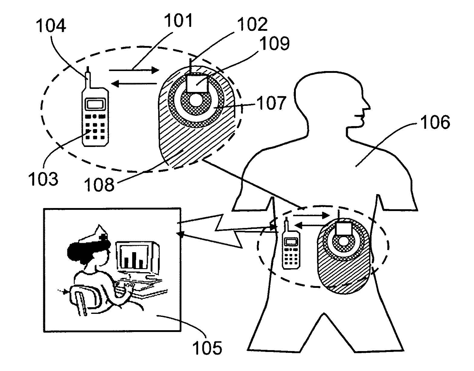
BACKGROUND OF THE INVENTION[0001]1. Field of the Invention[0002]The present invention relates to a method, a dressing and a dressing assembly for detecting a leak between the dressing and an electrically conductive object by measuring the changes in capacitance between the dressing and the electrically conductive object.[0003]2. Description of the Related Art[0004]Some stoma patients experience problems with leakage from ostomy bags or leakage of body fluids from the ostomy. Origins of the leakages can be skin folds developed underneath the adhesive of a bandage, a scar near a stoma not providing good adhesion or presence of a humid spot prior to attaching the adhesive and thereby preventing the adhesive from obtaining good adhesion to the skin or the leak may occur in time as the adhesive properties of the bandage deteriorate. A leakage for a stoma patient can be embarrassing and highly inconvenient. Also wound care patients can have problems with leakages from a dressing. A patien...

Claims


Application Information

Patent Timeline
IPC IPC(8): A61F5/445A61F13/00G08B21/00
CPCA61F5/445A61F5/443A61F13/42A61F13/02A61F13/00051A61F13/0246A61F5/4404A61B5/746
Inventor THIRSTRUP, CARSTENNILSSON, DANIELPRANOV, HENRIKLADING, LARS
Owner COLOPLAST AS
Learn More