Gas-phase hydrotreating of middle-distillates hydrocarbon feedstocks

a technology of gas-phase hydrotreating and feedstocks, which is applied in the direction of aromatic hydrocarbon hydrogenation, separation processes, chemical/physical/physicochemical processes, etc., can solve the problems of incomplete catalyst utilization, high cost, and inability to achieve purity improvement, so as to maximize catalyst utilization, enhance hydrotreating reactions, and maximize cell-per-square-inch density

Inactive Publication Date: 2010-02-11
HER MAJESTY THE QUEEN & RIGHT OF CANADA REPRESENTED BY THE MIN OF NATURAL RESOURCES
View PDF29 Cites 18 Cited by
  • Summary
  • Abstract
  • Description
  • Claims
  • Application Information

AI Technical Summary

Benefits of technology

[0008]In certain exemplary embodiments, the desired intensification of hydrotreating is achieved by carrying out the hydrotreating reactions entirely in the gas-phase rather than in mixed-phase (gas and liquid) flow conditions. Such gas-phase flow conditions may be achieved by mixing a distillates hydrocarbon feedstock and a hydrogen-rich treating gas in a proportion that causes full vaporization of the distillates at the operating temperature and pressure optimized for the hydrotreating reactor operation. The gaseous mixture of the vaporized distillates and treating gas then flows through a hydrotreater reactor filled with a catalyst that is preferably, although not necessarily, in the form of a monolith or other structured catalyst form. The monolith is preferably prepared in such a way that its entire volume consists of a porous supported or bulk catalytic material. The dimensions of channels in the monolith may be optimized to fit as much catalyst as possible into the available volume of the hydrotreater reactor vessel and preferably to maintain a pressure drop of approximately 0.3 bars / m, which is a typical value for commercial trickle-bed operations, or less (and preferably much less). This may be achieved by maintaining the total open face area of the monolith at a suitable level while maximizing the cell-per-square-inch density at the highest level that is possible to manufacture. Such a design maximizes catalyst utilization. The gas-phase hydrotreating process of such exemplary embodiments is therefore fundamentally different from conventional mixed-phase hydrotreating, and it has been experimentally found to offer significant enhancements to the hydrotreating reactions (such as HDS and HDN).
[0010]Thus, in this exemplary embodiment, instead of simply increasing the pressure of the reactant mixture to compensate for the pressure drop caused by the use of catalyst particles in smaller and more densely packed form, the ratio of middle-distillates feedstock to treating gas is reduced (gas to liquid ratio increased) sufficiently under existing operating conditions of temperature and pressure to ensure that the middle distillate is evaporated completely to gas or vapor before it contacts the catalyst, thereby increasing the effectiveness of the catalyst in the hydrotreating reactions (because the components of the mixture are all in the gaseous phase and consequently diffuse more rapidly and completely to the active surfaces of the catalyst). The process is made more commercially feasible if the structure of the catalyst is made such that the pressure drop is reduced or minimized compared to the use of densely packed catalyst particles, e.g. by employing a structured catalyst bed of optimized design. Thus, exemplary embodiments achieve desired improvements through improved overall reaction rates and / or better catalyst utilization (without increased pressure drop).
[0013]In the apparatus, the catalyst bed preferably contains a structured catalyst body to minimize the pressure drop as the reaction gas passes through the catalyst bed.

Problems solved by technology

Middle distillates fractions (like most products derived from crude oil) normally contain undesirable compounds containing heteroatoms such as sulfur, nitrogen, and oxygen, that can cause air pollution and other problems (e.g. deactivation of catalytic converters, corrosion, etc.) when burned.
However, such purity improvements, while possible, are expensive to achieve.
For example, in hydrotreating of middle distillates, the rate of diffusion into the catalyst particle is typically controlling the overall hydrodesulphurization (or other) rate, which results in incomplete catalyst utilization and limited overall conversion.
Better catalyst utilization can be achieved by using catalyst particles of a smaller effective size, but this increases the pressure drop across the catalyst bed and results in a need for additional gas compression capacity that significantly increases the capital cost of the installation.
The optimum compromise between the catalyst size and the cost of the hydrotreater equipment is usually determined during the hydrotreater design phase, and the resulting design typically leads to incomplete catalyst utilization.

Method used


Image

  • Gas-phase hydrotreating of middle-distillates hydrocarbon feedstocks
  • Gas-phase hydrotreating of middle-distillates hydrocarbon feedstocks
  • Gas-phase hydrotreating of middle-distillates hydrocarbon feedstocks

Examples


example 1

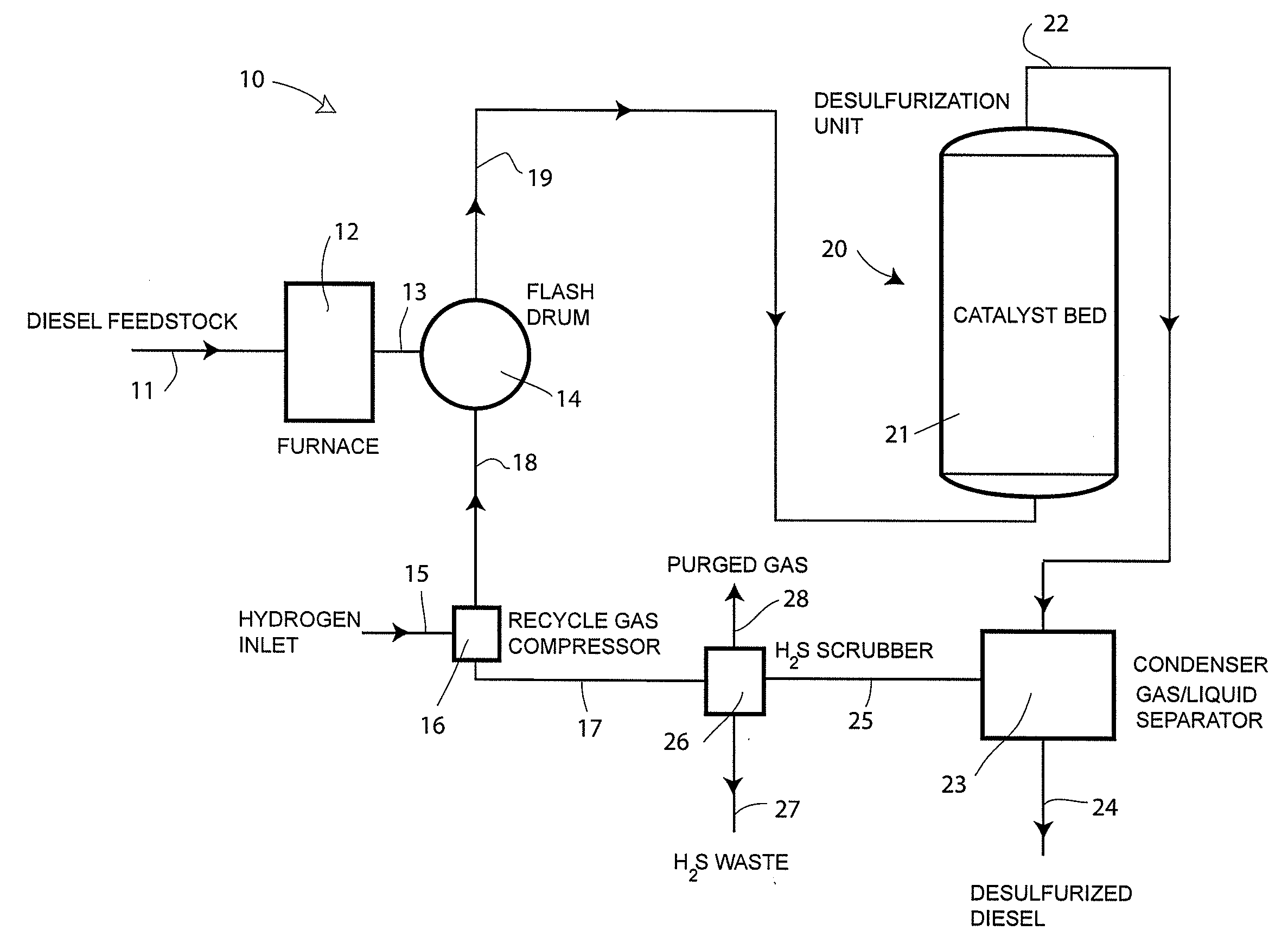
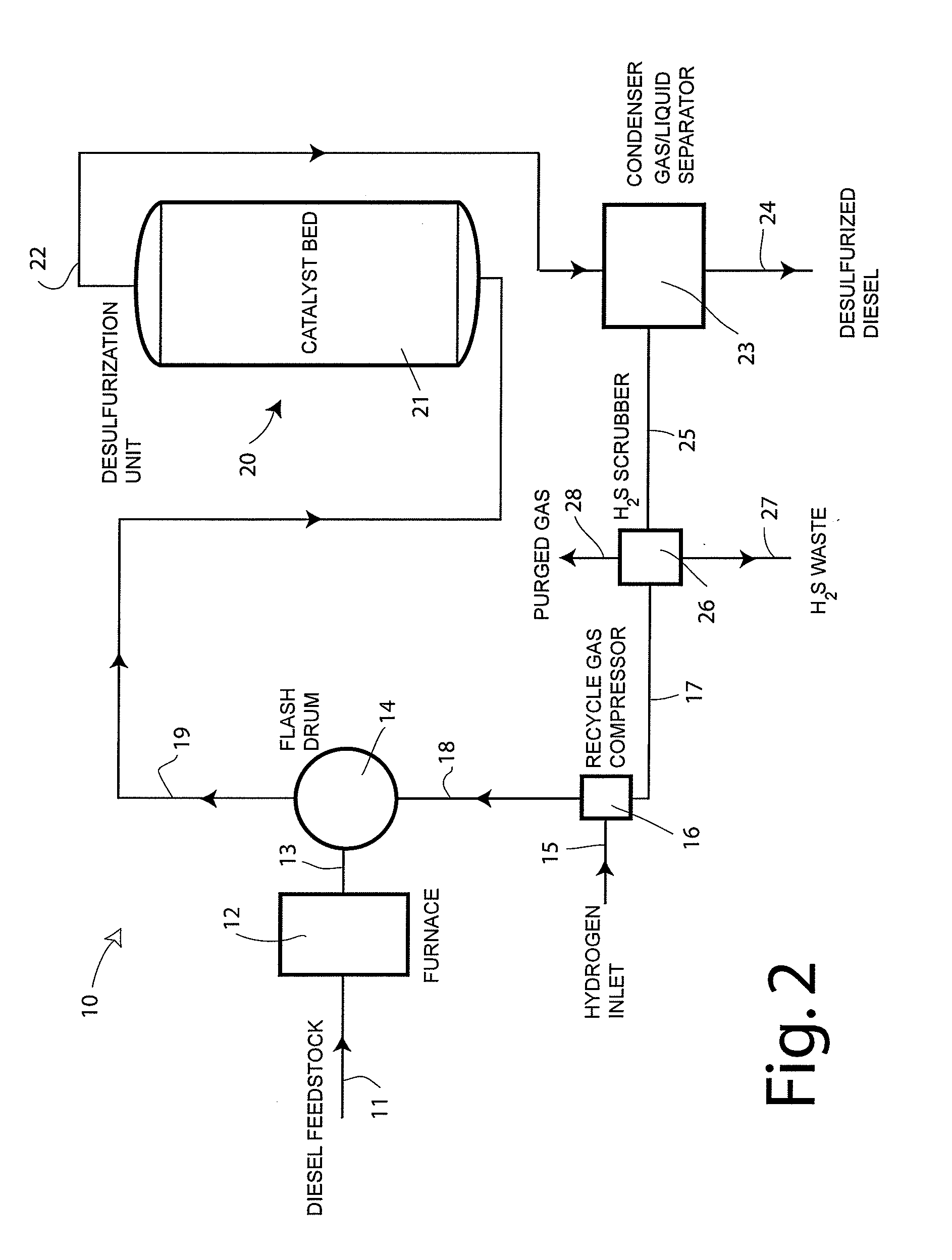
[0063]The experiments in this Example were conducted in a pilot plant (pilot plant PP19 of the National Centre for Upgrading Technology (NCUT), Alberta, Canada). The feed used was light cycle oil (from Petro-Can's Edmonton Refinery in Alberta, Canada) which had a density of 0.9338, total sulphur content of 1.12 wt % and total nitrogen content of 702 wppm. The catalyst used was a commercial NiMo / Al2O3 hydrotreating catalyst and 30 ml of the catalyst was packed in the reactor with a 1:1 volumetric ratio dilution of 0.2 mm glass beads. The main feed properties are listed in Table 1 below.

TABLE 1Properties of Petro-Can LCODensity (15° C.), g / ml0.9336Carbon, wt %88.24Hydrogen, wt %10.49Total sulphur, wppm11178Total nitrogen, wppm702.3SimDis (SimulatedDistillation), ° C.IBP (Initial Boiling Point)126.410 wt %225.930 wt %256.550 wt %288.670 wt %327.390 wt %375.1FBP (Final Boiling Point)439.9

[0064]The main objective of this Example was to prove the concept of the gas phase hydrotreating ope...

example 2

[0065]The experiments in this Example were also conducted in a pilot plant (NCUT's PP12). The feed used was light cycle oil (from Irving Oil), which had a density of 0.9708, total sulphur of 1.24 wt % and total nitrogen of 611 wppm. The catalyst used was a commercial NiMo / Al2O3 hydrotreating catalyst; 100 ml of catalyst was packed in the reactor with 1:1 volumetric ratio dilution of 0.2 mm glass beads. The main feed properties are listed in Table 3 below. The operating conditions were: temperature=380° C., pressure=70 bars, and LHSV velocity=1.0 / h. The gas / oil ratios ranged from 403 to 5054 NL / kg.

[0066]The sulphur and nitrogen conversion data are shown in Table 4 below and the corresponding plots are showing in FIGS. 8 and 9, respectively. It is observed that the sulphur and nitrogen conversion increases significantly when the gas / oil ratio increases from 403 NL / kg to 2522 NL / kg. After that, the sulphur conversion tended to reach a plateau with further increase in gas / oil ratio. The...


PUM

PropertyMeasurementUnit
boiling pointaaaaaaaaaa
temperatureaaaaaaaaaa

Abstract

A method of subjecting a middle-distillate hydrocarbon feedstock to a hydrotreating reactions to remove heteroatoms and / or hydrogenate aromatics, and apparatus therefor. The method comprising heating a liquid middle distillates hydrocarbon feedstock to produce a heated feedstock, mixing the heated feedstock with a hydrogen-containing treating gas to produce a mixture, and bringing the mixture into contact with a hydrotreating catalyst at an elevated temperature and an elevated pressure effective for hydrotreating the feedstock. The hydrogen-containing gas is mixed with the heated feedstock in a ratio effective to fully vaporize the liquid feedstock at the elevated temperature and pressure before the feedstock is contacted with said hydrotreating catalyst. Ideally, the mixture is passed through a catalyst bed creating a pressure drop in the gas mixture equal to or less than 0.3 bar / m. Such a catalyst bed may be made of structured catalysts, such as monolithic catalysts.

Description

BACKGROUND OF THE INVENTION[0001](1) Field of the Invention[0002]This invention relates to the refining of middle-distillates of hydrocarbons derived from crude oil or other sources into blending components of diesel fuel. More particularly, the invention relates to the hydrotreating of such distillates for the purpose of reducing the content of organic compounds containing such heteroatoms as sulfur, nitrogen and oxygen (e.g. to reduce diesel fuel contaminants), and / or for the purpose of reducing the content of aromatic hydrocarbons (e.g. to improve the ignition characteristics of diesel fuel).[0003](2) Description of Related Art[0004]Diesel oil has been an important fuel for internal combustion engines for decades and its use has been steadily increasing because it offers improved mileage in modern engines. Diesel oil is conventionally obtained as a suitable blend of various middle-distillates fractions of hydrocarbons (blending components) derived from a variety of crude material...

Claims


Application Information

Patent Timeline
Patent Type & Authority Applications(United States)
IPC IPC(8): C10G45/00B01J19/00
CPCB01D53/77B01D2256/16B01D2257/304B01D2257/406B01J8/0453C10G2300/4012C10G45/02C10G45/44C10G49/002C10G2300/1048C10G2300/4006B01J8/0492
Inventor RING, ZBIGNIEW E.CHEN, JINWEN
Owner HER MAJESTY THE QUEEN & RIGHT OF CANADA REPRESENTED BY THE MIN OF NATURAL RESOURCES
Why Eureka
Try Eureka