
System and Method for Fabricating Ceramic Substrates

a technology of ceramic substrates and systems, applied in the direction of machines/engines, filtration separation, separation processes, etc., can solve the problems of unavoidable trade-off between porosity and strength, and achieve the effect of optimizing strength and porosity performan

Inactive Publication Date: 2010-02-25
GE02 TECH INC
View PDF101 Cites 18 Cited by
  • Summary
  • Abstract
  • Description
  • Claims
  • Application Information

AI Technical Summary

Benefits of technology

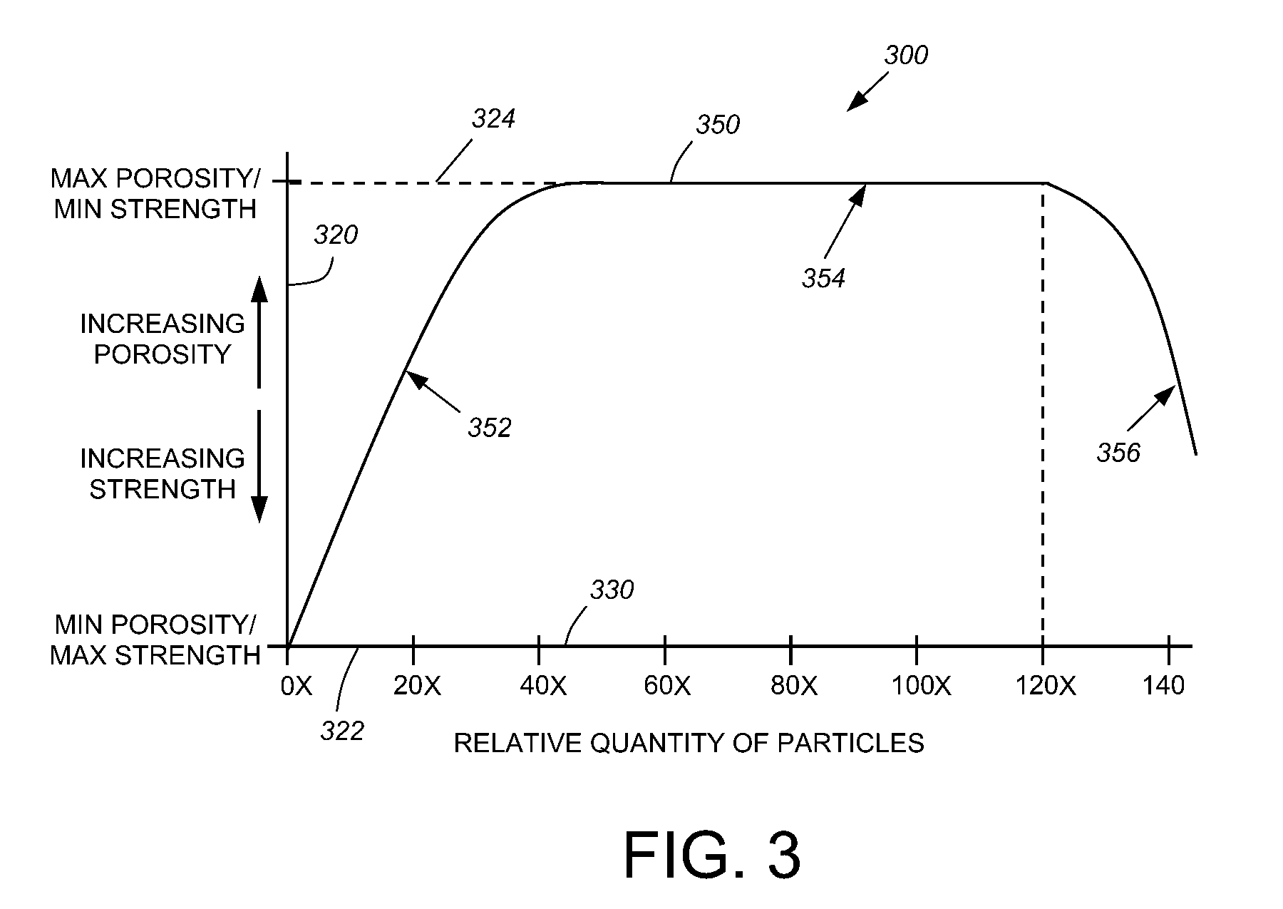
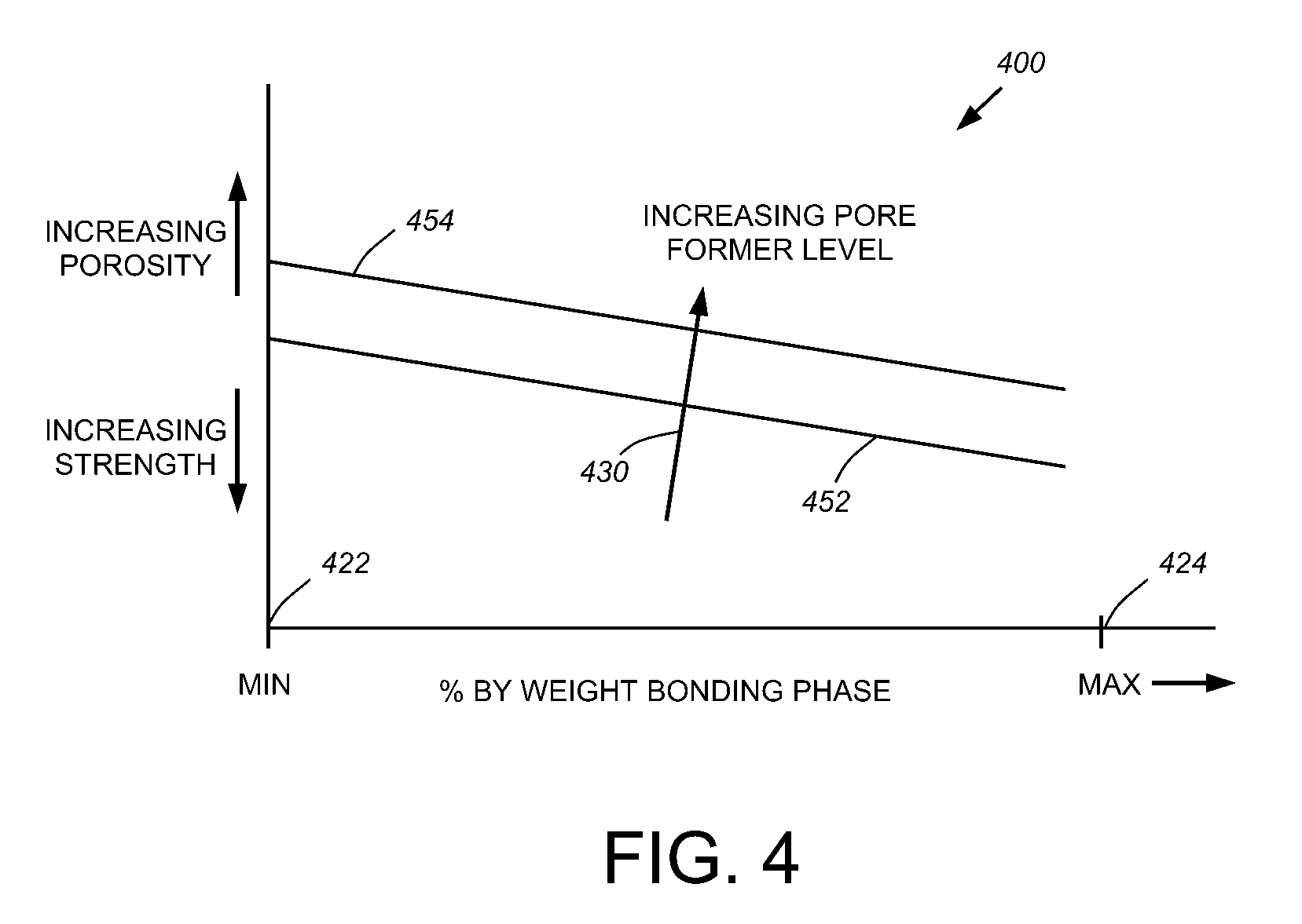
This patent describes a system and method for making a porous ceramic substrate with specific strength and porosity properties. The system identifies the factors that affect each component in the mixture and adjusts them to achieve the desired strength and porosity performance. The components include a solvent, fiber, binder, pore former, and bonding phase. By controlling these factors, the system can create an optimized strength and porosity performance. The resulting substrate has a unique structure with gaps between the particles and a solid lattice. The system can also compensate for changes in strength and porosity by adjusting the controllable factors of each component. The optimal mixture includes between 5 and 45 percent pore former and between 2 and 33 percent bonding phase. The inorganic bonding phase can include bentonite and glass. The reduction of the pore former can increase porosity without significantly reducing strength, while the adjustment of the bonding phase can increase porosity without reducing strength.

Problems solved by technology

Because more pores tend reduce the number of sintered bonds in the fiber lattice, there is an unavoidable tradeoff between porosity and strength.

Method used


Image

  • System and Method for Fabricating Ceramic Substrates
  • System and Method for Fabricating Ceramic Substrates
  • System and Method for Fabricating Ceramic Substrates

Examples


Embodiment Construction

A. Overview of Substrate Fabrication

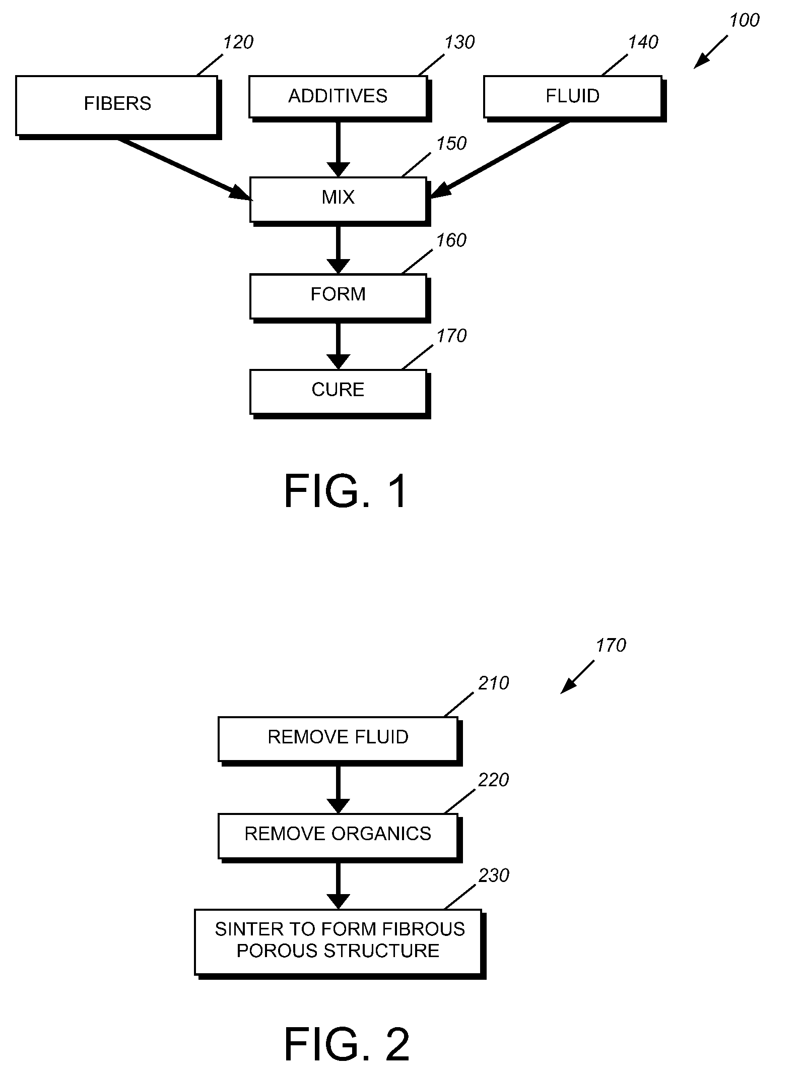
[0036]By way of further background, and referring to FIG. 1, a procedure 100 for fabricating a fiber-based substrate according to the present invention is shown. Similar fabrication processes are disclosed in commonly-assigned patent applications, including U.S. patent Ser. No. 11 / 831,398 entitled “A fiber based ceramic substrate and method of fabricating the same,” and U.S. patent Ser. No. 11 / 323,429, entitled “An extruded porous substrate and products using the same,” both of which are incorporated herein by reference. Generally, fibers 120, with additives 130 and a solvent fluid (typically water) 140, are mixed 150 into a plastic batch that is formed into a green substrate 160 and fired / cured 170. Note that various embodiments of the substrate can be fabricated to form fiber-based substrates having alternative compositions using any number of different fiber compositions, additives, and solvents. In an exemplary embodiment, mullite fiber can be...


PUM

PropertyMeasurementUnit
particle sizeaaaaaaaaaa
temperature propertiesaaaaaaaaaa

Abstract

This invention provides a system and method for establishing proper quantities of components in the initial mixture to be used in the fabrication of a porous ceramic substrate. The components typically consist of a solvent, a bulk fiber such as mullite, an organic binder for use in extrusion of the green substrate, a glass / clay bonding phase that bonds the fibers upon high-temperature curing and a pore former that defines gaps between the particles and is vaporized out of the substrate during curing. By identifying the controllable factors related to each of the components, and adjusting the factors to vary the resulting strength and porosity of the cured substrate, an optimized strength and porosity performance can be achieved. The controlling factors for each component include its relative weight percent in the mixture. The fiber component is also controlled via fiber diameter, diameter uniformity, and fiber length-to-diameter aspect ratio. Likewise, pore former is also controlled by particle size and shape and particle density. The bonding phase may also be controlled based upon its contribution to the viscosity at sintering temperature.

Description

CROSS-REFERENCE TO RELATED APPLICATIONS[0001]This application is a continuation-in-part to U.S. patent application Ser. No. 11 / 322,777 entitled “Process for Extruding a Porous Substrate” filed Dec. 30, 2005, which claims priority to U.S. provisional patent application Ser. No. 60 / 737,237 entitled “System for Extruding a Porous Substrate” filed Nov. 16, 2005. This application also claims priority to U.S. provisional patent application No. 61 / 057,169, entitled “System and Method for Fabricating Ceramic Substrates” filed May 29, 2008. The entire contents of U.S. patent application Ser. No. 11 / 322,777, provisional patent applications Ser. No. 60 / 737,237 and provisional patent application Ser. No. 61 / 057,169 are each incorporated herein by reference.FIELD OF THE INVENTION[0002]This invention relates to systems and methods for fabricating ceramic substrates useful for insulation, filtration and / or high-temperature chemical reaction processing, such as a catalytic host, and more particular...

Claims


Application Information

Patent Timeline
Patent Type & Authority Applications(United States)
IPC IPC(8): C03C10/14
CPCB01D39/2089B01D46/0001B01D46/2418B01D46/2448F02M25/06B01D2239/10B01D2257/7022F01N2330/06B01D2046/2433B01D46/2429
Inventor LIU, JAMES JENQZUBERI, BILALCARTY, WILLIAM M.DAHL, RACHEL A.WEINSTEIN, JERRY C.PILLAI, SUNILKUMAR C.GORDON, TIMOTHYMARSHALL, JAMES
Owner GE02 TECH INC
Learn More