Onsite integrated production factory

Active Publication Date: 2010-03-04
M HIKARI & ENERGY LAB
View PDF1 Cites 25 Cited by
  • Summary
  • Abstract
  • Description
  • Claims
  • Application Information

AI Technical Summary

Benefits of technology

[0075]In the present invention, two methods are adopted as the method of producing metal sodium. One of these methods is a method in which a salt water solution containing a salt or rock salt or salt lake water is electrolyzed to produce caustic soda, which is then subjected to molten salt electrolysis to produce metal sodium. This reason is that this method of producing metal sodium through the production of caustic soda is more decreased in total cost and there are larger demands for caustic soda and hydrochloric acid produced as byproducts in other processes in the factory.
[0076]Although caustic soda is usually a starting material of soda industries, metal sodium is produced via caustic soda in the present invention because abundant electric power can be supplied by water wheel/windmill power generation on the ocean or wind power generation on the land. The other method is a method in which a common salt is directly subjected to molten salt electrolysis to produce sodium. Particularly, in the present invention, sodium oxalate produced in the ethanol plant is poured into the brine to remove calcium in the brine, and hydrochloric acid is poured into the precipitate calcium oxalate to recover oxalic acid and make calcium chloride free. However, when a mixed salt prepared by adding about 40% of calcium chloride to sodium chloride as a catalyst is subjected to molten salt electrolysis, the temperature of the electrolytic bath is dropped to about 600° C. from about 800° C. Though caustic soda and hydrogen are not produced as byproducts, it is hard to abandon this method because this method is superior in workability and safety. Both the metal sodium products obtained in these two methods are transported to the hydrogen supply facilities on the land, where water and sodium are reacted with each other to generate hydrogen, and caustic soda which is a reaction residue obtained after the production of hydrogen is supplied as it is as the raw material of soda industries. Specifically, this implies that caustic soda which is the raw material of soda industries can be supplied without cost. The annual consumption of caustic soda in our country is as large as 4450000 ton which is the third in rank. When comparing this with the annual power consumption (1.1 trillion kWh), the power consumption is incredibly larger. For this, it is considered that if the equipment of the present invention is in such a situation that it is fully operated, the supply of caustic soda is excessive. For this, the supply of caustic soda to soda industries is limited taking the balance between the demand and supply into account, a sodium fuel cycle for reproducing metal sodium can be established by subjecting caustic soda of the reaction residue to molten salt electrolysis by using the electric power obtained wind power generation. This sodium fuel cycle is a system in which fuel is produced endlessly to reuse it in the same manner as in the nuclear fuel cycle for reproducing uranium and plutonium by retreating spent nuclear fuel in an atomic power plant. However, the sodium fuel cycle recommended by the present invention is safe because no radioactive waste like the nuclear fuel cycle is produced. Also, uranium is deposited only in limited areas in the world and is limited in reserve like fossil fuels so that there is a fear that it is exhausted in dozen years or so in the future. In contrast with these small resources, sodium is present inexhaustively as salts in sea water and also exists as a rock salt on the land abundantly. The sodium is a fuel in rich resources and can be supplied all over the world. Also, metal sodium has a specific gravity of 0.971, so that it is lighter than water and it can

Problems solved by technology

The current procurement of energy sources is limited to places rich in resources from an economical point of view and the problem is how to transport the energy resources economically to a consumer place.
However, the development

Method used


Image

  • Onsite integrated production factory
  • Onsite integrated production factory
  • Onsite integrated production factory

Examples


Embodiment Construction

[0098]Several embodiments of the present invention will be explained in detail with reference to FIG. 1 to FIG. 21.

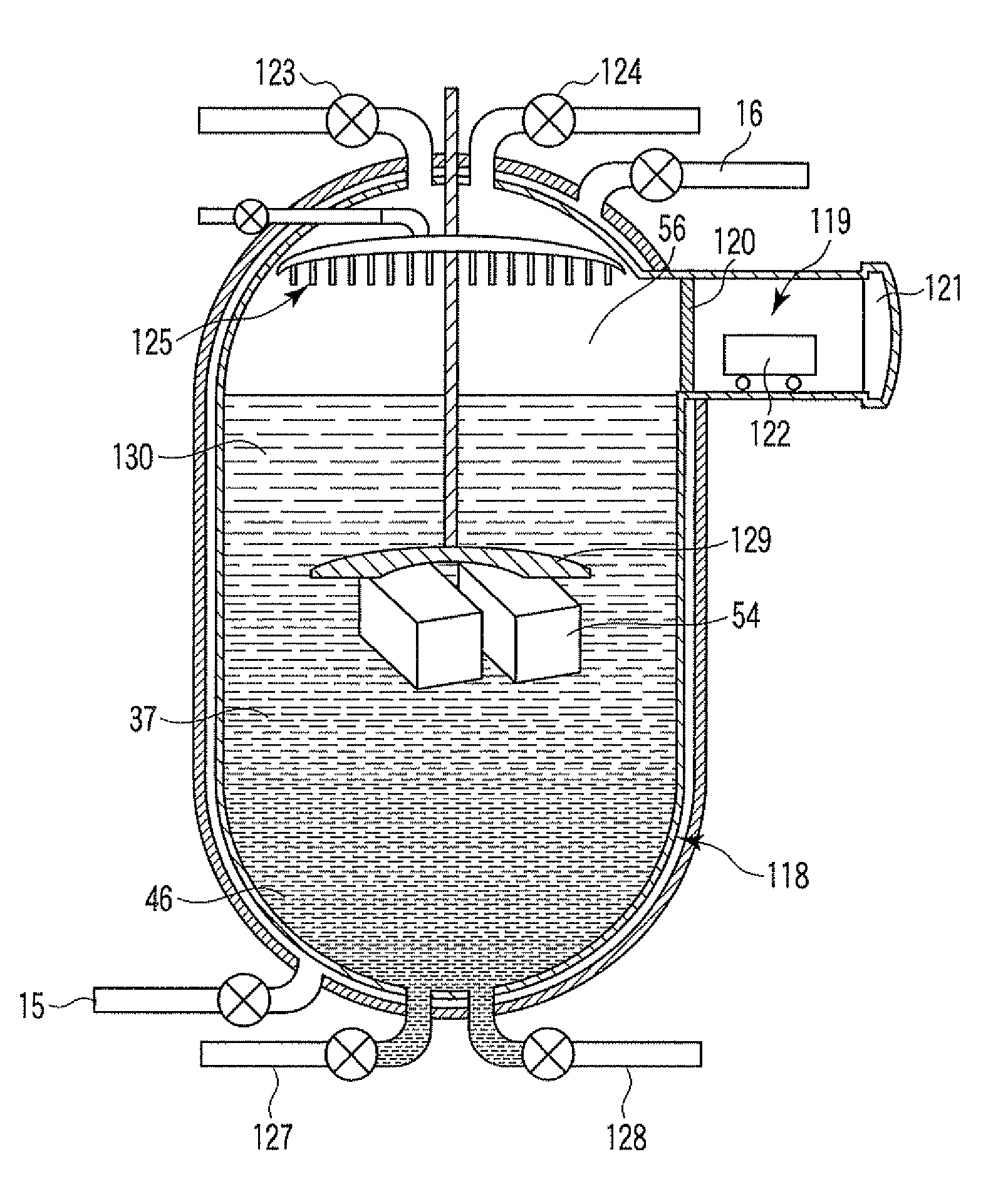
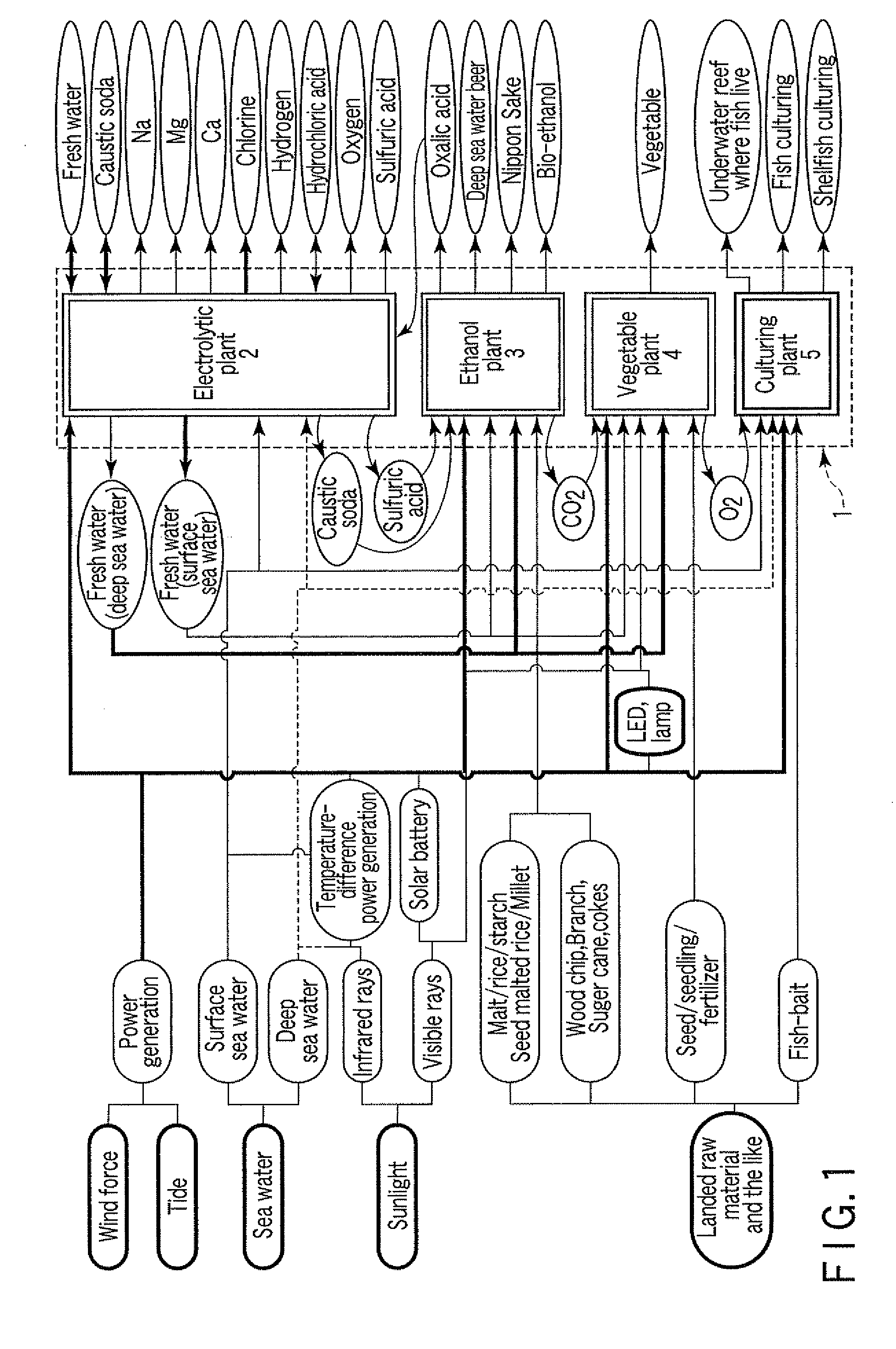
[0099]FIG. 1 is a schematic view showing an embodiment of the present invention. As shown in FIG. 1, an onsite integrated production factory 1 according to the present invention includes an electrolytic plant 2, an ethanol plant 2, a vegetable plant 3 and a culturing plant 4 and these factories 2 to 4 are installed in a floating body vessel floated on the ocean, a structure on the coast or a structure on the land adjacent to the seashore. The energy obtained by fluid energy power generation utilizing wind and tide, temperature-difference power generation utilizing hot water heated by the infrared ray of sunlight or high-temperature hot spring water such as submarine hot spring and coastal hot spring, and sea water or river water, or solar cell power generation utilizing the visible rays of sunlight or the like are supplied to the integrated production factory 1. The mai...


PUM


Abstract

Using electric power obtained by marine wind force and a tide, sea water is electrolyzed to produce fresh water, sodium, magnesium, calcium, potassium, caustic soda, chlorine, hydrochloric acid, sulfuric acid, hydrogen, oxygen or the like, at the same time, unloaded malts, saw dust and the like are fermented to brew ethanol, carbon dioxide generated here is used for photosynthesis to culture vegetables and oxygen generated here is supplied to a fish preserve and an under reef where fish live to culture fishes and also returned to sea water dropped in the concentration of oxygen to suppress the generation of a red tide.

Description

CROSS REFERENCE TO RELATED APPLICATIONS[0001]This is a Continuation Application of PCT Application No. PCT / JP2008 / 058500, filed May 7, 2008, which was published under PCT Article 21(2) in Japanese.[0002]This application is based upon and claims the benefit of priority from prior Japanese Patent Applications No. 2007-126324, filed May 11, 2007; and No. 2008-082335, filed Mar. 27, 2008, the entire contents of both of which are incorporated herein by reference.BACKGROUND OF THE INVENTION[0003]1. Field of the Invention[0004]The present invention relates to an onsite integrated production factory and particularly to an onsite integrated factory provided with an electric power generating means utilizing natural energy and comprising an electrolysation plant, an ethanol plant, a vegetable plant and a fish / shellfish-culturing plant, which are integrated on a site.[0005]2. Description of the Related Art[0006]In every nation of the world, the reconstruction of industries such as energies, cau...

Claims


Application Information

Patent Timeline
IPC IPC(8): C25B15/00
CPCA01G31/00Y02E60/368B01D61/025B01D61/48C01D1/04C01D1/40C02F1/42C02F1/441C02F1/461C02F1/66C02F9/00C02F2103/08C12C5/002C12F3/02C12G3/02C25B1/00A01K63/042Y02W10/33Y02W10/37Y02P20/133Y02A20/142Y02A20/131Y02A20/141Y02A20/144F24S20/20C12G3/022Y02A20/124Y02E10/40Y02E60/36Y02P60/60Y02P80/20C25B1/04C12G3/021
Inventor MURAHARA, MASATAKA
Owner M HIKARI & ENERGY LAB
Why Eureka
Try Eureka