Heat-dissipating resin composition, substrate for LED mounting, reflector, and substrate for LED mounting having reflector portion

a technology of heat dissipation resin and resin composition, which is applied in the direction of solid-state devices, light and heating equipment, chemical instruments and processes, etc., can solve the problems of reduced brightness of led elements, short life or the like, and achieve excellent moldability and impact resistance, excellent heat resistance and light resistance, and excellent whiteness

Inactive Publication Date: 2010-03-25
TECHNO POLYMER CO LTD
View PDF6 Cites 70 Cited by
  • Summary
  • Abstract
  • Description
  • Claims
  • Application Information

AI Technical Summary

Benefits of technology

[0008]According to the heat-dissipating resin composition of the present invention, moldability and impact resistance are excellent. And both in the case of a substrate for LED mounting and in the case of a reflector, heat dissipation, insulation, heat resistance and light resistance are superior while an LED element emits light.
[0009]In the case where the content of the iron oxide is 0.01% or less by weight in the thermally conductive filler, the composition has excellent whiteness and thus the light reflective characteristic is more excellent.
[0010]Additionally, in the case where the thermally conductive filler is of boron nitride, the heat dissipation, insulation, heat resistance and light reflective characteristic while an LED element emits light are more excellent. Accordingly, in the substrate for LED mounting and the reflector comprising the heat-dissipating resin composition of the present invention, since the temperature increase caused by heat generated when the LED element emits light is prevented by heat dissipation, does not cause the brightness to be reduced, and this makes it possible to extend the life of the LED eleme

Problems solved by technology

However, since an LED element generates heat when it emits light, the temperature of such an LED illumination device is incre

Method used


Image

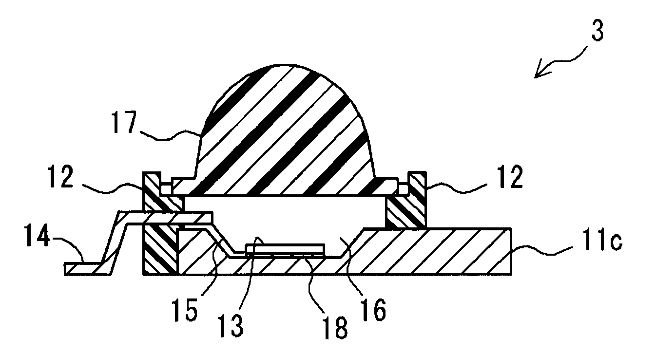
  • Heat-dissipating resin composition, substrate for LED mounting, reflector, and substrate for LED mounting having reflector portion
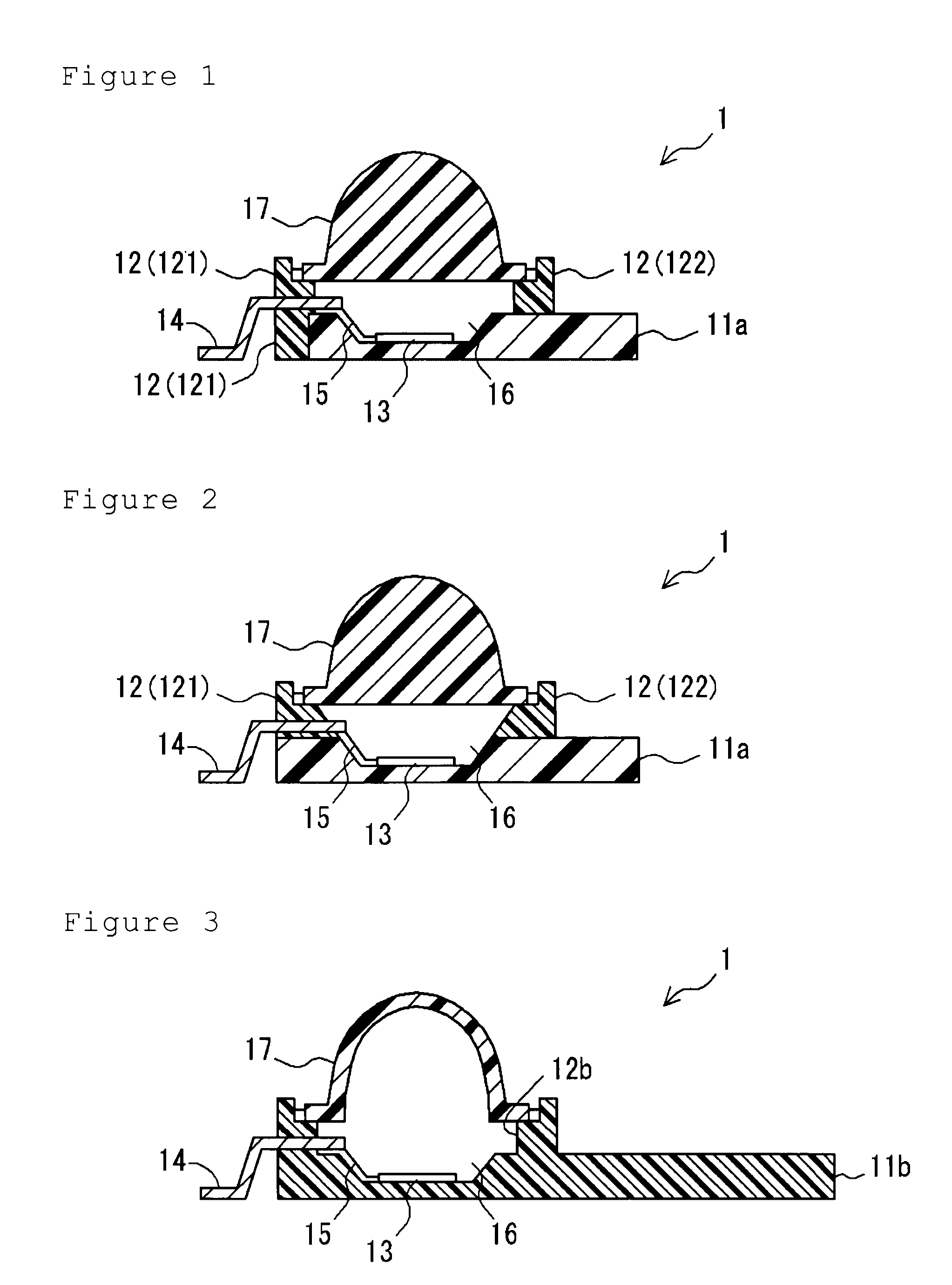
  • Heat-dissipating resin composition, substrate for LED mounting, reflector, and substrate for LED mounting having reflector portion
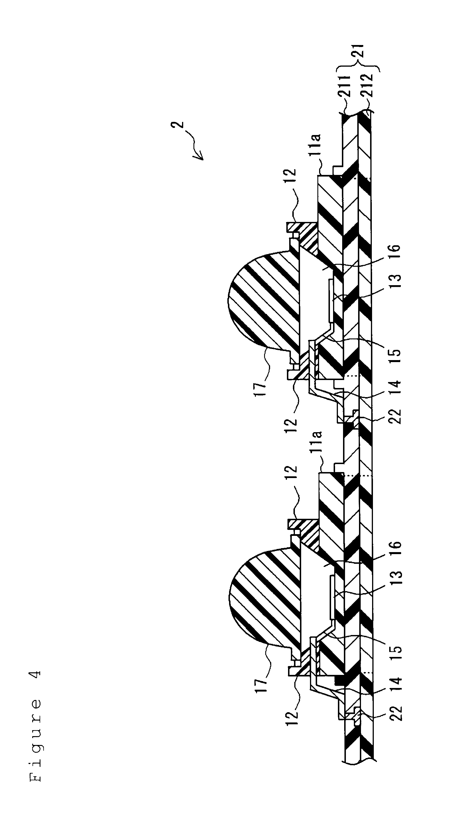
  • Heat-dissipating resin composition, substrate for LED mounting, reflector, and substrate for LED mounting having reflector portion

Examples


examples

[0212]Hereinafter, the present invention is described in detail using Examples. The present invention is in no way limited by these Examples. In addition, “part” and “%” in the examples are based on weight unless otherwise indicated.

1. Production and Evaluation of Heat-Dissipating Resin Composition

[0213]The starting materials for compositions used in the following Examples and Comparative examples will be shown.

1-1. Thermoplastic Resin

[0214](1) A1; Copolymer-type polybutylene terephthalate (modified PBT provided with flexibility; a copolymer of dimethyl telephtalate, 1,4-butanediol and poly tetramethylene glycol)

[0215]“NOVADURAN 5505S” (trade name) manufactured by Mitsubishi Engineering Plastics Co. Ltd. was used. Glass transition temperature thereof is 27° C.

(2) A2; Homo-Type Polybutylene Terephthalate

[0216]“NOVADURAN 5007” (trade name) manufactured by Mitsubishi Engineering Plastics Co. Ltd. was used. Glass transition temperature thereof is 30° C.

(3) A3; Homo-Type Polyethylene Ter...

examples 16 to 22

(1) Method of Producing Heat-Dissipating Resin Composition

[0257]The thermoplastic resin, the thermally conductive filler, the ultraviolet absorber, the light stabilizer and the inorganic white pigment in the proportion shown in Table 3 were charged into a mixer to mix for five minutes. After that, they were melt, kneaded and extruded, using an extruder (Type “BT-40-S2-30-L” manufactured by PLABOR Co., Ltd.) and a slightly kneading type screw, at a screw speed of 100 rpm at a cylinder temperature of 260° C. to obtain a pellet (heat-dissipating resin composition).

(2) Evaluation Method

[0258]The pellets thus obtained were used to perform tests for evaluating the above items [1] to [10]. The results of the tests were shown in Table 3.

TABLE 3Example16171819202122Heat-MixedThermoplastic resindissipatingamountA160606060606060resin(parts)Thermally conductive fillercompo-B740404040404040sitionUltraviolet absorberD1  0.5  0.5  0.5Light stabilizerE1  0.5  0.5E2  0.5  0.5Inorganic white pigmentF...

example 23

[0259]The heat-dissipating resin composition of Example 1 was used to heat with a circular silicone rubber heater 5 (40 mm in diameter) placed in the middle of the surface of the test piece 4 made in the above item [1] by applying a predetermined current at an input voltage of 10V through a watt density of 0.5 W / cm2 (see FIG. 6). After a lapse of 10 minutes, the temperature of the surface of the silicon rubber was 55° C. At the same time, the temperature measured at a position that was marked “X” and located at the upper left corner in FIG. 6 was 48° C.

[0260]It was found that since the heat-dissipating resin composition had a higher thermal conductivity than that of only a resin and a higher thermal emissivity than that of a metal, its temperature was likely to be decreased and the heat was likely to be dissipated.


PUM

PropertyMeasurementUnit
Temperatureaaaaaaaaaa
Fractionaaaaaaaaaa
Fractionaaaaaaaaaa

Abstract

The objective of the present invention is to provide a heat-dissipating resin composition that is used for forming a substrate for LED mounting or a reflector provided on the substrate for LED mounting and is excellent in heat dissipation, electrical insulation, heat resistance and light resistance while an LED element emits light, a substrate for LED mounting and a reflector comprising the composition. The present composition comprises a thermoplastic resin such as modified PBT and a thermally conductive filler consisting of scaly boron nitride or the like, and has thermal deformation temperature of 120° C. or higher, a thermal conductivity of 2.0 W/(m·K) or higher, and a thermal emissivity of 0.7 or higher.

Description

TECHNICAL FIELD[0001]The present invention relates to a heat-dissipating resin composition and a molded article comprising the heat-dissipating resin composition. Specifically, the present invention relates to a heat-dissipating resin composition which is suitable for formation of a substrate for LED mounting and a reflector provided on this substrate for LED mounting that are constructing a surface-mounting LED package and to molded articles exemplified above.BACKGROUND ART[0002]Since an LED element is conventionally compact and have a long life and low power consumption, it is utilized as a light source for an indication light or the like. Moreover, since an LED element of higher brightness has recently been produced at a relatively low price, it is considered to be utilized as a light source that can replace a fluorescent lamp and an incandescent light bulb. In the case where an LED element is applied as such a light source, in order to obtain a higher illumination, a surface-mou...

Claims


Application Information

Patent Timeline
IPC IPC(8): C09K5/00H01L33/32H01L33/56H01L33/58H01L33/60H01L33/62H01L33/64
CPCC08L101/12F28F21/06H01L33/56H01L33/641H01L33/644H01L2924/0002H05K1/0373H01L2924/00
Inventor FUJIOKA, SHINSUKEKITADA, FUSAMICHI
Owner TECHNO POLYMER CO LTD
Why Eureka
Try Eureka