Method and apparatus for producing nanofibers and polymer web

a technology of applied in the field of methods and apparatus for producing nanofibers and polymer webs, can solve the problems of inability to realize polymer webs, inability to produce nanofibers, and inability to achieve high-porous polymer webs, etc., to achieve high productivity, stably and efficiently produced, and flow more effectively

Active Publication Date: 2010-03-25
PANASONIC CORP
View PDF8 Cites 27 Cited by
  • Summary
  • Abstract
  • Description
  • Claims
  • Application Information

AI Technical Summary

Benefits of technology

[0025]Furthermore, the production apparatus of the nanofibers of the present invention includes: a conductive rotating container which is rotatably supported and which has a plurality of small holes with a distance provided from a rotating shaft center in a radial direction; polymer solution supply means for supplying into the rotating container a polymer solution in which a polymer material is dissolved in a solvent; rotation drive means for rotatably driving the rotating container; charging means for imparting an electric charge to the polymer solution discharged from the small holes of the rotating container; orientation and flow means, which is arranged on one side in a shaft center direction of the rotating container, for orienting and making charged nanofibers produced from the polymer solution discharged from the small holes of the rotating container flow toward the other side in the shaft center direction of the rotating container; and a control unit for controlling the polymer solution supply means, the rotation drive means, the charging means, and the orientation and flow means. The advantageous effects of the above-described method for producing nanofibers can be enjoyed by performing such method. Furthermore, the charging means may be configured by a high-voltage generation means which applies a high voltage to the rotating container, or which applies a high voltage to a member, such as the collector for the nanofibers, which is arranged with an interval with respect to the rotating container so that an electric field is generated between the rotating container and the member.
[0026]Furthermore, the orientation and flow means preferably has a reflecting electrode applied with a voltage with the same polarity as the electric charge of the polymer solution discharged from the small holes of the rotating container, and / or blowing means for blowing the nanofibers from the one side to the other side in the shaft center direction of the rotating container. If the orientation and flow means has the reflecting electrode, the nanofibers charged with a charge by the reflecting electrode can be reliably oriented and made to flow, and there is no risk of the flow of the polymer solution being hindered by the charge of the reflecting electrode, so that the nanofibers can be produced stably and efficiently. Furthermore, if the orientation and flow means has blowing means, the nanofibers from the production step can be oriented and made to flow more effectively by being ridden on the flow of air. In addition, the evaporated solvent is rapidly discharged due to the flow of air, so that the solvent concentration in the surrounding atmosphere does not become high. This allows the evaporation of the solvent to occur smoothly, so that the electrostatic explosion action can be reliably obtained, and the desired nanofibers can be reliably produced.
[0027]Furthermore, it is preferred that the rotating container is configured by a cylindrical container having the plurality of small holes on its peripheral surface, or a tubular container on which the small holes are arranged so that their rotation diameters decrease moving from one side to the other side in a shaft center direction of the rotating container. If the rotating container is configured by a cylindrical container, a large amount of nanofibers can be uniformly produced at a time from the whole periphery, so that a high productivity can be secured, and since the shape and structure are simple, equipment costs can be reduced. Furthermore, if the rotating container is configured by the above-described tubular container, due to the difference in the centrifugal force received by the polymer solution discharged from the respective small holes, the nanofibers formed by the small holes on the one side flow toward an outer position away in the radial direction, and the nanofibers formed by the small holes on the other side flow toward an inner position on the other side in the radial direction. Thus, the nanofibers discharged from the respective sides do not overlap, so that a flow region cross-sectional shape of the nanofibers can be made to approximate a circle rather than a narrow-width doughnut shape.
[0028]Furthermore, to focus the cross-sectional shape of the flow region of the nanofibers from a doughnut shape into an arbitrary cross-sectional shape, such as a shape in which the center hollow portion become smaller or a rectangular cross-section, a focusing electrode for focusing the tubular flow region of the nanofibers may be arranged on at least a shaft center portion and a periphery portion of the tubular flow region of the nanofibers on the other side of the shaft center direction of the rotating container, applying a voltage of the same or different polarity which is lower than that of the rotating container to the focusing electrode arranged on the shaft center portion, and applying a voltage of the same polarity as the rotating container is applied to the focusing electrode arranged on the periphery portion.
[0029]Furthermore, a supply tube for supplying the polymer solution may be inserted from a shaft center aperture portion on one end of the cylindrical container, and the tip of this supply tube may be formed in a roughly L-shape in the cylindrical container. By doing this, the polymer solution can be supplied into the rotating container without the risk of the polymerization solution leaking from the shaft center aperture portion on one end of the cylindrical container, even if the orientation of the cylindrical container is arbitrarily changed so that the flow direction of the produced nanofibers is not only a horizontal direction, but is downwards or upwards.
[0030]Furthermore, means for controlling the amount of the polymer solution contained in the rotating container at a constant level may be provided. By doing this, the centrifugal force acting on the polymer solution extruded from the small holes of the rotating container is constant, and the polymer solution can be uniformly discharged in a filamentous state, so that the uniform nanofibers can be produced. One example of such means for controlling the amount of the polymer solution in the rotating container at a constant level is a configuration which includes contained amount detection means for detecting the amount of the polymer solution contained in the rotating container, and supply control means for controlling the polymer solution supply means based on the detected contained amount.

Problems solved by technology

However, in conventional electrospinning, only one to a few nanofibers can be produced from the tip of a single nozzle.
Therefore, productivity when trying to produce a highly porous polymer web does not improve, and thus such a polymer web could not be realized.

Method used


Image

  • Method and apparatus for producing nanofibers and polymer web
  • Method and apparatus for producing nanofibers and polymer web
  • Method and apparatus for producing nanofibers and polymer web

Examples


embodiment 1

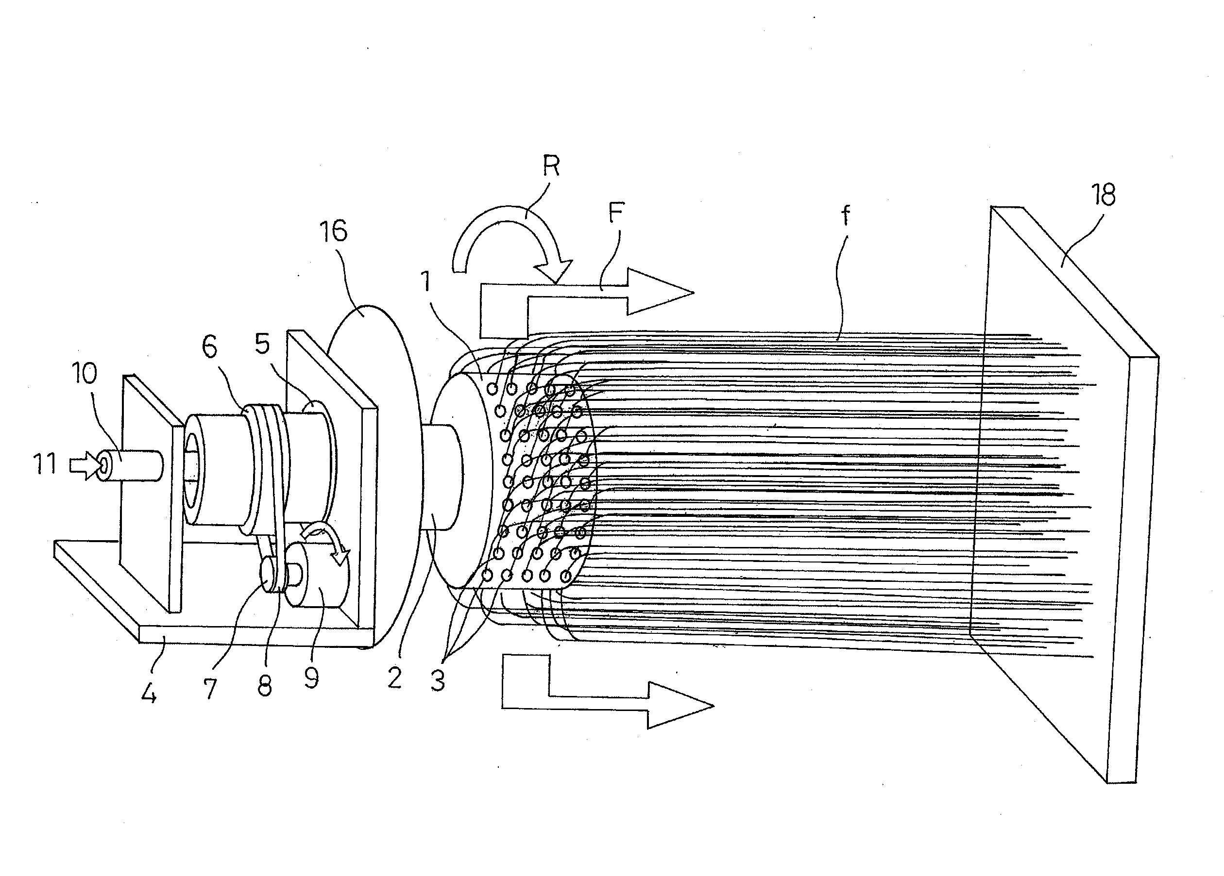
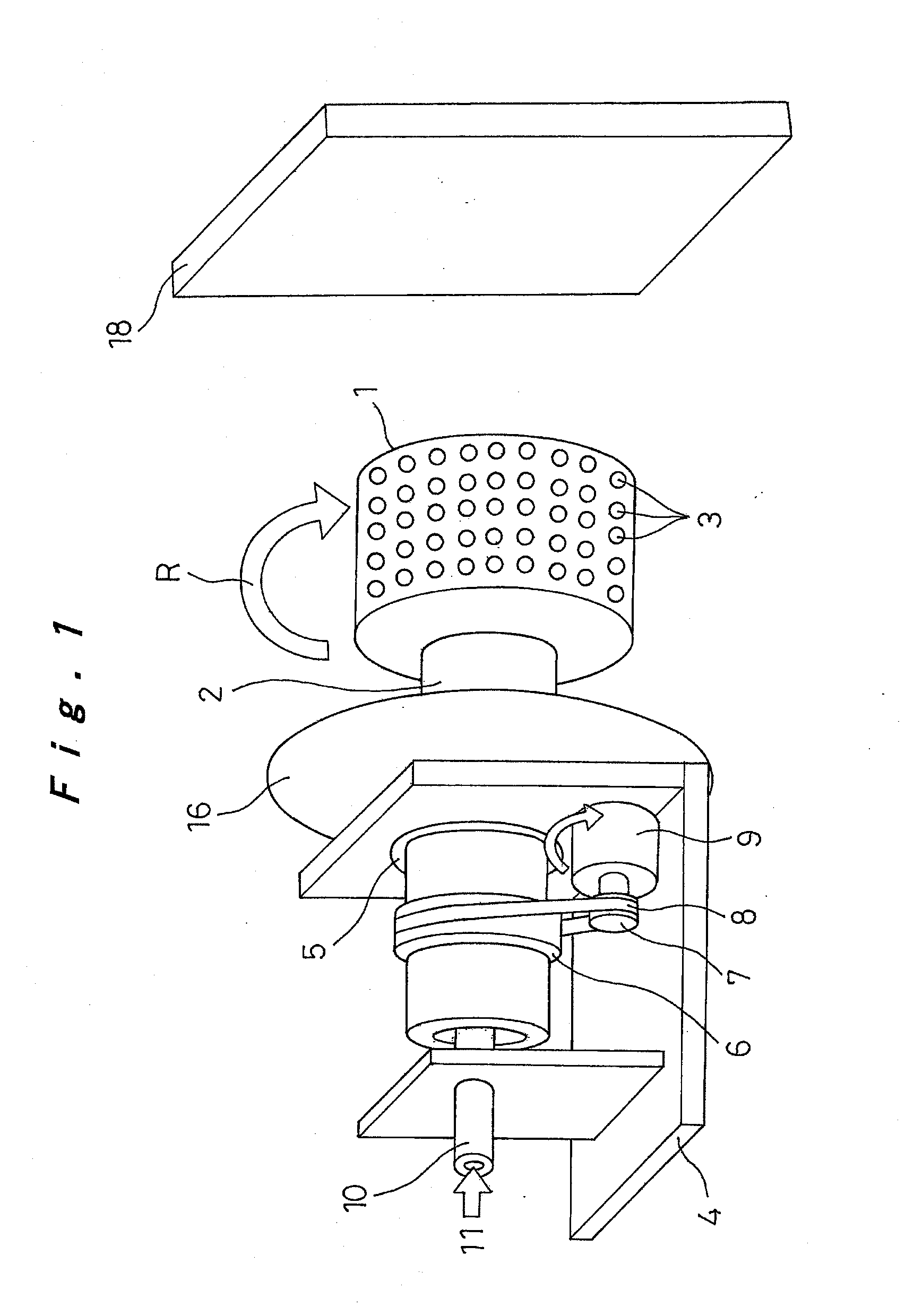
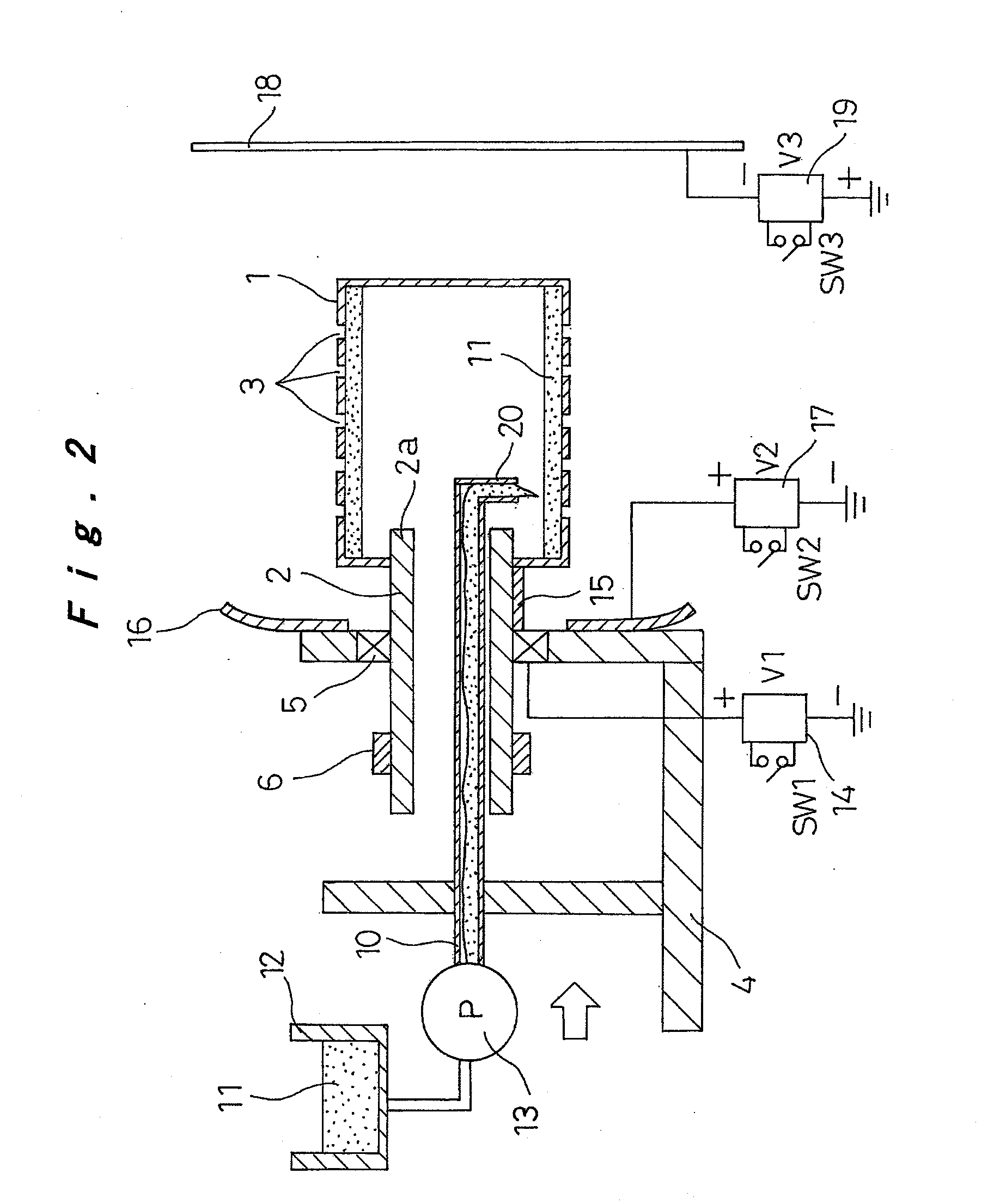
[0060]First, Embodiment 1 of the production apparatus of the polymer web of the present invention will be described with reference to FIGS. 1 to 6C.

[0061]In FIGS. 1 to 3, reference numeral 1 denotes a cylindrical container with a diameter of 20 to 500 mm as a rotating container. The end of a rotating cylinder 2 passes through the shaft center of one end of the cylindrical container 1. The cylindrical container 1 is thus integrally fixed so as to be rotatably supported in the direction of arrow R around the shaft center by the rotating cylinder 2. The rotating cylinder 2 is formed from a material having high electrical insulation properties. The other end of the cylindrical container 1 is closed, and multiple small holes 3 with a diameter of about 0.01 to 2 mm are formed on a peripheral surface at a pitch distance of a few mm. The small holes 3 may be formed by holes which are directly open to the peripheral wall of the cylindrical container 1, or may be formed by a nozzle member wit...

embodiment 2

[0077]Next, Embodiment 2 of the polymer web production apparatus of the present invention will be described with reference to FIGS. 7 to 10. In the following description of the embodiments, constituent elements which are the same as in the previous embodiment are denoted using the same reference numerals, and a description thereof is omitted. Here, the points of difference will mainly be described.

[0078]In the above-described embodiment, an example was described in which a predetermined amount of the polymer solution 11 was supplied into the cylindrical container 1 based on the amount of the polymer web to be produced. However, in the present embodiment, the amount of the polymer solution 11 contained in the cylindrical container 1 is detected, and the supply pump 13 is operated and controlled based on that detected amount, so that a roughly constant amount of the polymer solution 11 is contained in the polymer solution 11.

[0079]In FIG. 7, contained amount detection means 25 is arra...

embodiment 3

[0083]Next, Embodiment 3 of the polymer web production apparatus of the present invention will be described with reference to FIG. 11.

[0084]In the present embodiment, as illustrated in FIG. 11, blowing means 34 is arranged between the cylindrical container 1 and the reflecting electrode 16 on one side thereof. Specifically, blowing blades 35 are installed on the rotating cylinder 2 at a position between the reflecting electrode 16 and the cylindrical container 1. As the rotating cylinder 2 rotates, air is blown toward the other side of the cylindrical container 1 as shown by arrow D.

[0085]According to this configuration, solvent which has evaporated by the air blown by the blowing means 34 is rapidly discharged, so that the solvent concentration of the surrounding atmosphere does not become high. Thus, evaporation of the solvent proceeds smoothly, the electrostatic explosion effects can be reliably obtained, and desired nanofibers f can be reliably produced. Furthermore, the advanta...


PUM

PropertyMeasurementUnit
voltageaaaaaaaaaa
diameteraaaaaaaaaa
diameteraaaaaaaaaa

Abstract

Nanofibers are formed from a polymer material by rotating a conductive rotating container having a plurality of small holes while supplying a polymer solution formed by dissolving a polymer material in a solvent into the rotating container, charging the polymer solution discharged from the small holes of the rotating container by charging means, and drawing the discharged filamentous polymer solution by centrifugal force and an electrostatic explosion resulting from evaporation of the solvent. The nanofibers from this production step are oriented and made to flow from one side toward the other side in a shaft center direction of the rotating container by a reflecting electrode and / or blowing means, or those nanofibers are deposited, to produce a polymer web. The nanofibers and the polymer web using these nanofibers can be produced uniformly by a simple configuration with good productivity.

Description

TECHNICAL FIELD[0001]The present invention relates to a method and an apparatus for producing nanofibers formed from a polymer material and a highly porous polymer web obtained by depositing those nanofibers.BACKGROUND ART[0002]Conventionally, electrospinning (electric charge induced spinning) is known as a method for producing nanofibers formed from a polymer material which have a diameter in the order of submicrons. In conventional electrospinning, a polymer solution is supplied to a needle-like nozzle to which a high voltage is applied so that the polymer solution discharged as filaments from this needle-like nozzle is electrically charged. As the solvent of the polymer solution evaporates, the distance between these electric charges decreases, and the Coulomb force acting thereon increases. When this Coulomb force exceeds the surface tension of the filamentous polymer solution, the filamentous polymer solution is explosively drawn. This phenomenon, which is called electrostatic ...

Claims


Application Information

Patent Timeline
Patent Type & Authority Applications(United States)
IPC IPC(8): B29C47/92B29C47/00B29C48/92D04H3/02D04H3/16
CPCD01D5/0038D01D5/0069B29C47/92D04H3/02D04H3/166D01D5/18D04H1/56D04H1/728B29C48/92B29C2948/9259B29C2948/92657B29C2948/92828B29C2948/92866B29C2948/92952D01D5/00B82Y40/00
Inventor TAKAHASHI, MITSUHIROTAKEZAWA, MIKIOTOMINAGA, YOSHIAKIKUROKAWA, TAKAHIROISHIKAWA, KAZUNORISUMIDA, HIROTO
Owner PANASONIC CORP
Why Eureka
Try Eureka