Process temperature control in oxy/fuel combustion system

Inactive Publication Date: 2010-04-01
AIR PROD & CHEM INC
View PDF19 Cites 55 Cited by
  • Summary
  • Abstract
  • Description
  • Claims
  • Application Information

AI Technical Summary

Benefits of technology

[0011]An advantage of the present disclosure is the ability to control multiple steam temperatures in an oxy/fuel boiler.
[0012]A further advantage of the present d

Problems solved by technology

In addition, prolonged operation at higher-than-design steam temperatures can lead to exceeding design stress limits in boiler and turbine-cycle metal components, while prolonged operation at lower-than-design steam temperatures can result in moisture erosion damage in the final lower pressure stage.
This inaccuracy leads to penalties in thermal efficiency, power generation, and/or unit reliability.
This method is inherently unable to simultaneously control both the main (i.e. throttle) steam and reheat steam temperatures.
This inaccuracy leads to penalties in thermal efficiency, penalties in power generation, and/or penalties in unit reliability.
The challenges of maintaining independe

Method used


Image

  • Process temperature control in oxy/fuel combustion system
  • Process temperature control in oxy/fuel combustion system
  • Process temperature control in oxy/fuel combustion system

Examples


example

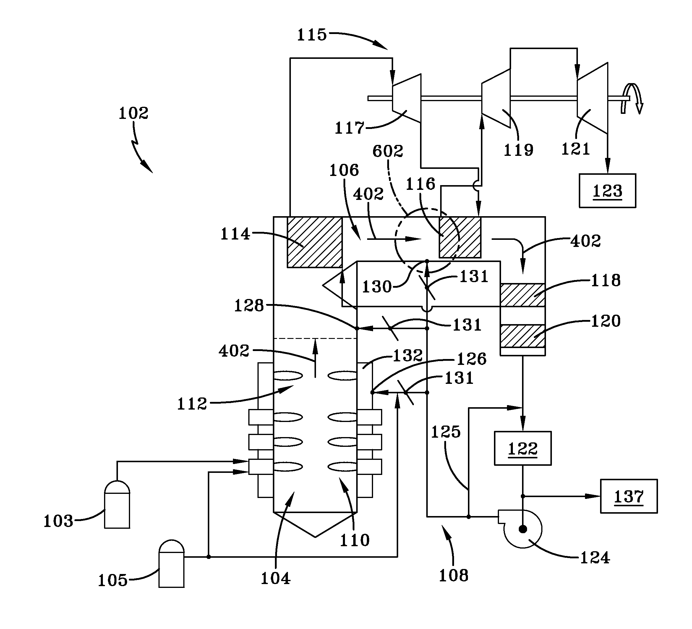
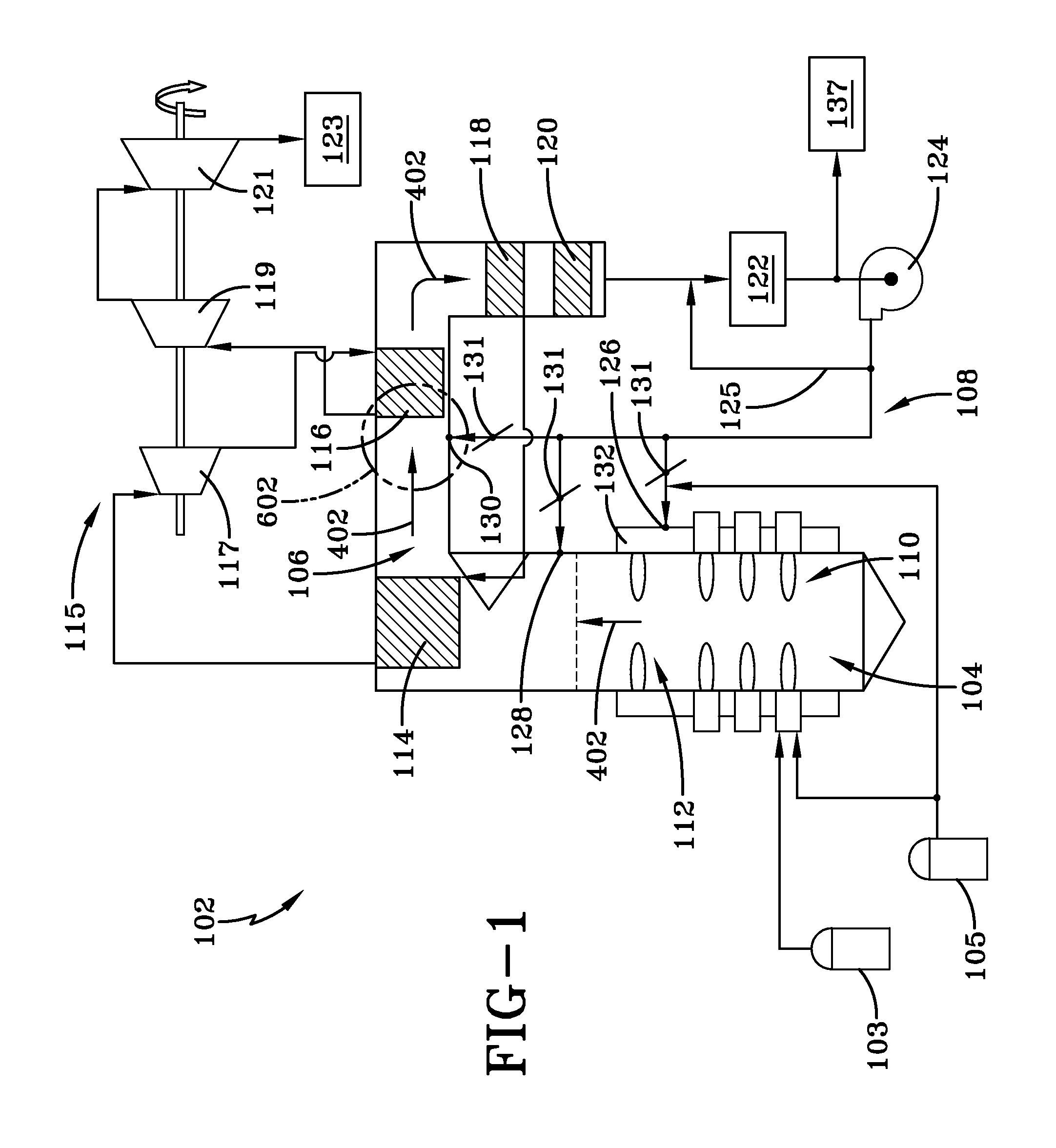
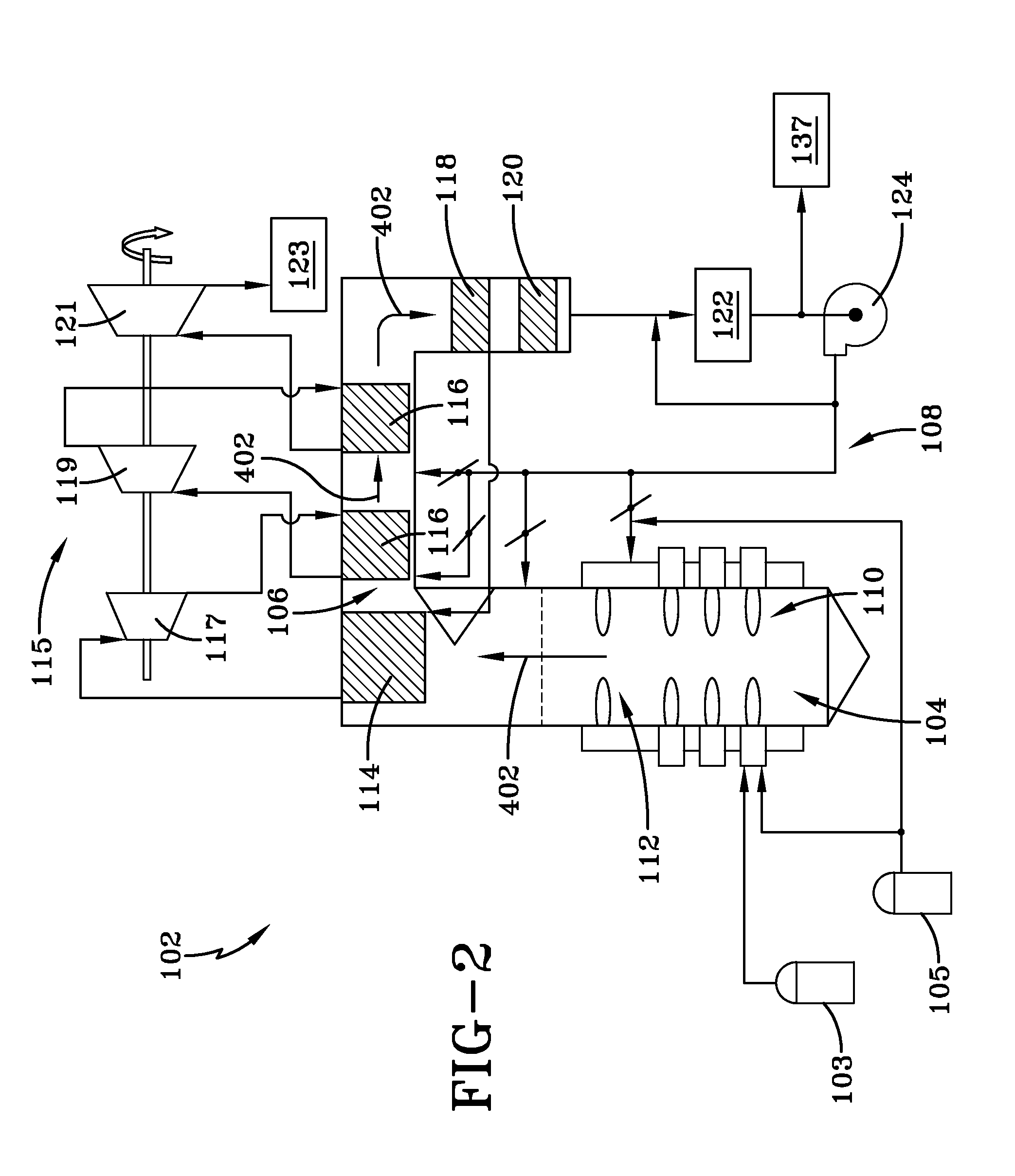
[0053]A known combustion system, specifically a boiler steam control system, includes an oxy / fuel boiler firing bituminous coal producing steam at sub-critical conditions to generate approximately 593 MW of gross electrical power using a single reheat Rankine cycle for the turbine. FIG. 12 illustrates a schematic representation of the flow of combustion fluid 402 through a portion of the known system. As illustrated in FIG. 12, the portion of the known system includes the furnace 104, the secondary superheater 114, and the reheat superheater 116 (also referred to as a reheater). To simplify analysis, the secondary superheater 114 and the reheat superheater 116 are each assumed to exist in a single heat transfer section. The furnace 104 is arranged and disposed to receive fuel, oxidizer, and recycled flue gas. Specifically, a first stream 902 of recycled flue gas is added to the general combustion zone of the furnace 104.

[0054]In addition, a second stream 904 of recycled flue gas is ...


PUM


Abstract

An oxy/fuel combustion system having a furnace arranged and disposed to combust a fuel to form a combustion fluid. The system further includes a convective section having at least one heat exchanger arranged and disposed to exchange heat between the combustion fluid and steam for use in a steam turbine. A flue gas recycle is arranged and disposed to recycle at least a portion of the combustion fluid as a recycled flue gas, the flue gas recycle having at least two expellant locations downstream of a primary combustion zone. The system includes a flow control mechanism that provides controlled amounts of the recycled flue gas to the at least two expellant locations to control temperature of the steam.

Description

CROSS-REFERENCE TO RELATED APPLICATIONS[0001]This Application is related to application Ser. No. ______, entitled “OXY / FUEL COMBUSTION SYSTEM WITH LITTLE OR NO EXCESS OXYGEN”, Attorney Docket No. 07228 USA, filed contemporaneously with this Application on Sep. 26, 2008, assigned to the assignee of the present disclosure and which is herein incorporated by reference in its entirety, application Ser. No. ______, entitled “COMBUSTION SYSTEM WITH STEAM OR WATER INJECTION”, Attorney Docket No. 07238 USA, filed contemporaneously with this Application on Sep. 26, 2008, assigned to the assignee of the present disclosure and which is herein incorporated by reference in its entirety, application Ser. No. ______, entitled “COMBUSTION SYSTEM WITH PRECOMBUSTOR”, Attorney Docket No. 07255 USA, filed contemporaneously with this Application on Sep. 26, 2008, assigned to the assignee of the present disclosure and which is herein incorporated by reference in its entirety, application Ser. No. ______,...

Claims


Application Information

Patent Timeline
IPC IPC(8): F23B80/02F23B10/00F23J15/00
CPCF01K3/20F22B35/002F23C9/003F23C9/08Y02E20/344F23C2202/50F23C2900/09001F23C2900/09002F23L7/007F23C2201/101Y02E20/34
Inventor D'AGOSTINI, MARK DANIEL
Owner AIR PROD & CHEM INC
Why Eureka
Try Eureka