

Extreme ultraviolet light source device, laser light source device for extreme ultraviolet light source device and method for controlling saturable absorber used in extreme ultraviolet light source device
- Summary
- Abstract
- Description
- Claims
- Application Information
AI Technical Summary
Benefits of technology
Problems solved by technology
Method used
Image

Examples
embodiment 1
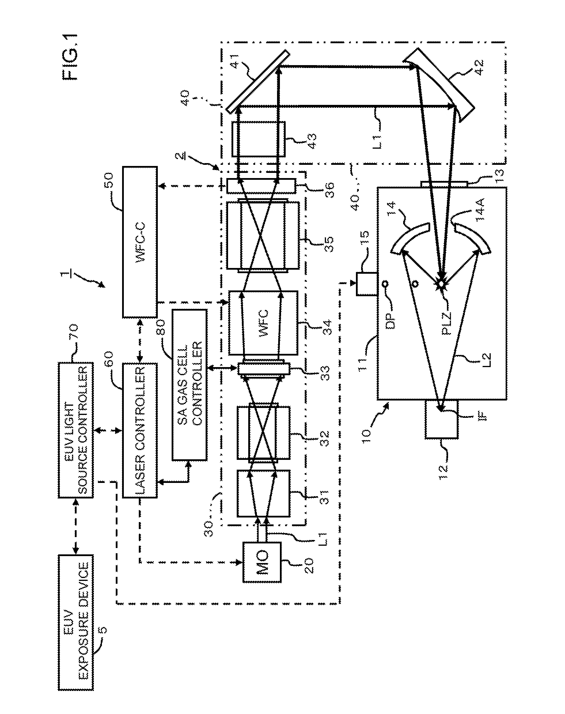
[0082]A first embodiment of the present invention will now be described with reference to FIG. 1 to FIG. 14. FIG. 1 is a block diagram depicting a general configuration of an EUV light source device 1.
[0083]The EUV light source device 1 has, for example, a chamber 10 for generating EUV light, a laser light source device 2 for supplying laser light to the chamber 10, and an EUV light source controller 70. The laser light source device 2 has, for example, a laser oscillator (Master Oscillator) 20 that determines the time waveform and repetition rate of the laser pulse, an amplification system 30, a focusing system 40, a wavefront correction controller (WFC-C) 50, and a laser controller 60. The EUV light source device 1 supplies EUV light to an EUV exposure device 5. In the following description and drawings, the wavefront compensation controller may be indicated as WFC-C (Wave Front Compensator Controller).
[0084]An overview of the chamber 10 will be described first. The chamber 10 has...
embodiment 2
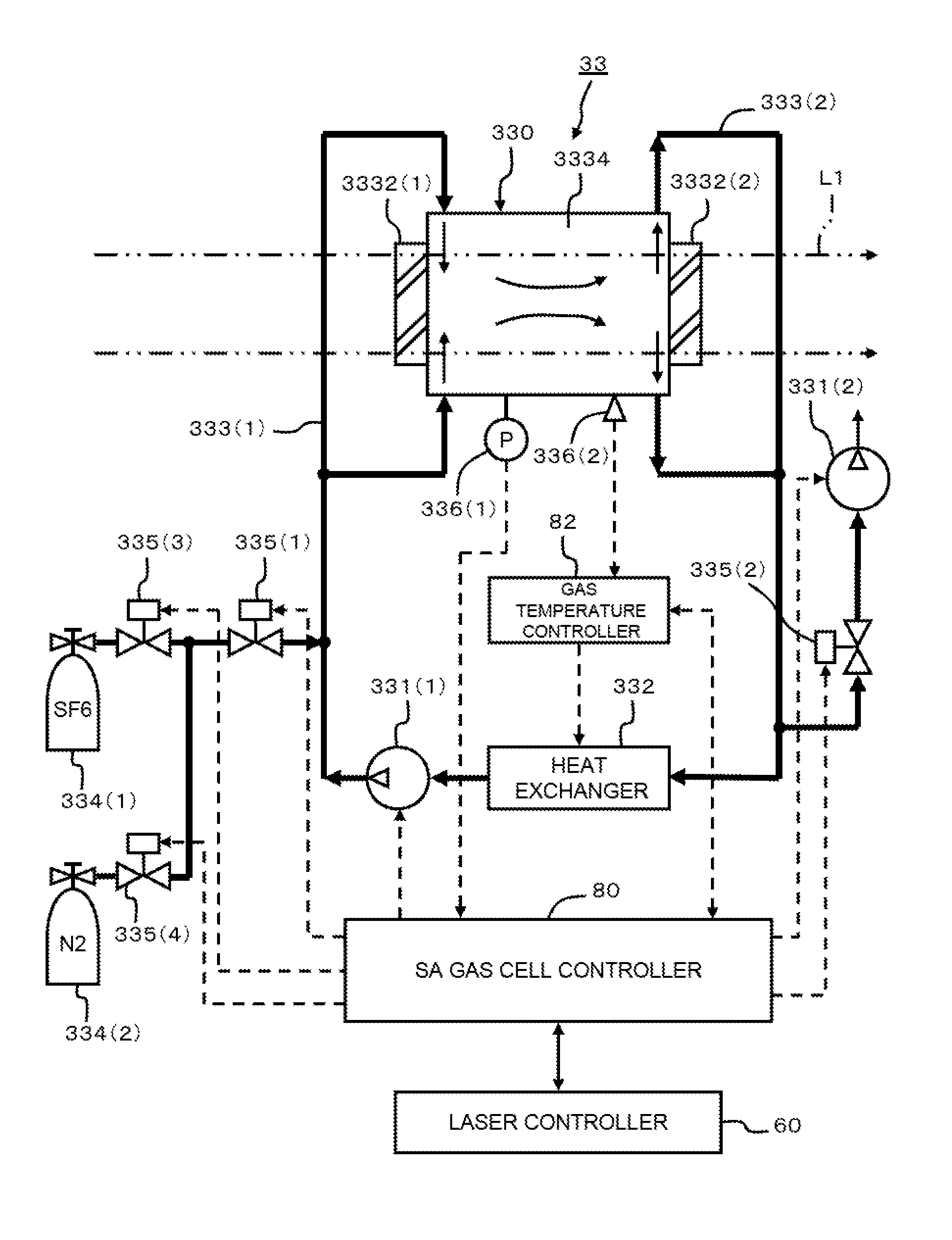
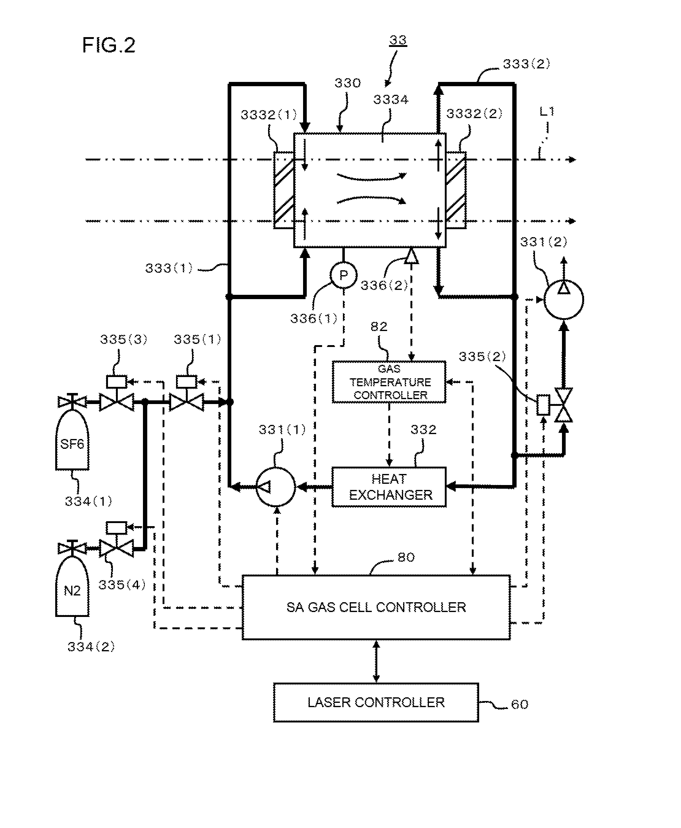
[0171]A second embodiment will now be described with reference to FIG. 15. Each of the following embodiments is a variant form of the first embodiment. Therefore the main differences from the first embodiment are described. In the present embodiment, a total of four inlets 3336 (1), 3336 (2), 3336 (3) and 3336 (4) are disposed so that the SA gas turns around the inner surface of each window 3332 (1) and 3332 (2). In the present embodiment, two outlets 3338 (1) and 3338 (2) are disposed between each window 3332 (1) and 3332 (2).
[0172]FIG. 15 is a diagram depicting an SA gas cell 330A. The drawing at the left in FIG. 15 shows a view from the input window 3332 (1), and the drawing at the center in FIG. 15 shows a side view of the SA gas cell 330A, and the drawing at the right in FIG. 15 shows a view from the output window 3332 (2).
[0173]Each inlet 3336 (1) and 3336 (2) at the input window side 3332 (1) is tilted at angle θ1, so that the SA gas turns and flows around the inner surface o...
embodiment 3
[0180]A third embodiment will now be described with reference to FIG. 16 and FIG. 17. In the present embodiment, porous cylindrical tubes 3340 (1) and 3340 (2), as “flow control elements”, are disposed in the windows 3332 (1) and 3332 (2) respectively, so that the mixed gas in the flow space 3334 uniformly moves to each outlet 3338 (1) to 3338 (4). FIG. 16 is a diagram depicting an SA gas cell 330B according to the present embodiment. FIG. 17 is a cross-sectional view of a porous cylindrical tube 3340.
[0181]As the drawing at the left in FIG. 16 shows, two outlets 3338 (1) and 3338 (2) are disposed in the diameter direction so as to be axially symmetric with respect to the optical axis of the laser beam. The porous cylindrical tube 3340 (1) is disposed between the outer circumference side of the inner face of the input window 3332 (1) and the outlets 3338 (1) and 3338 (2).
[0182]As the drawing at the right in FIG. 16 shows, two outlets 3338 (3) and 3338 (4) are also disposed in the di...
PUM
 Abstract
Description
Claims
Application Information