
Method and apparatus for pumping and operating optical parametric oscillators using dfb fiber lasers

a technology of optical parametric oscillators and fiber lasers, applied in optics, instruments, electromagnetic transmission, etc., can solve the problems of significant unfavorable heating of non-linear elements, and buildup of power circulation

Active Publication Date: 2010-04-08
LOCKHEED MARTIN ACULIGHT CORP
View PDF12 Cites 21 Cited by
  • Summary
  • Abstract
  • Description
  • Claims
  • Application Information

AI Technical Summary

Benefits of technology

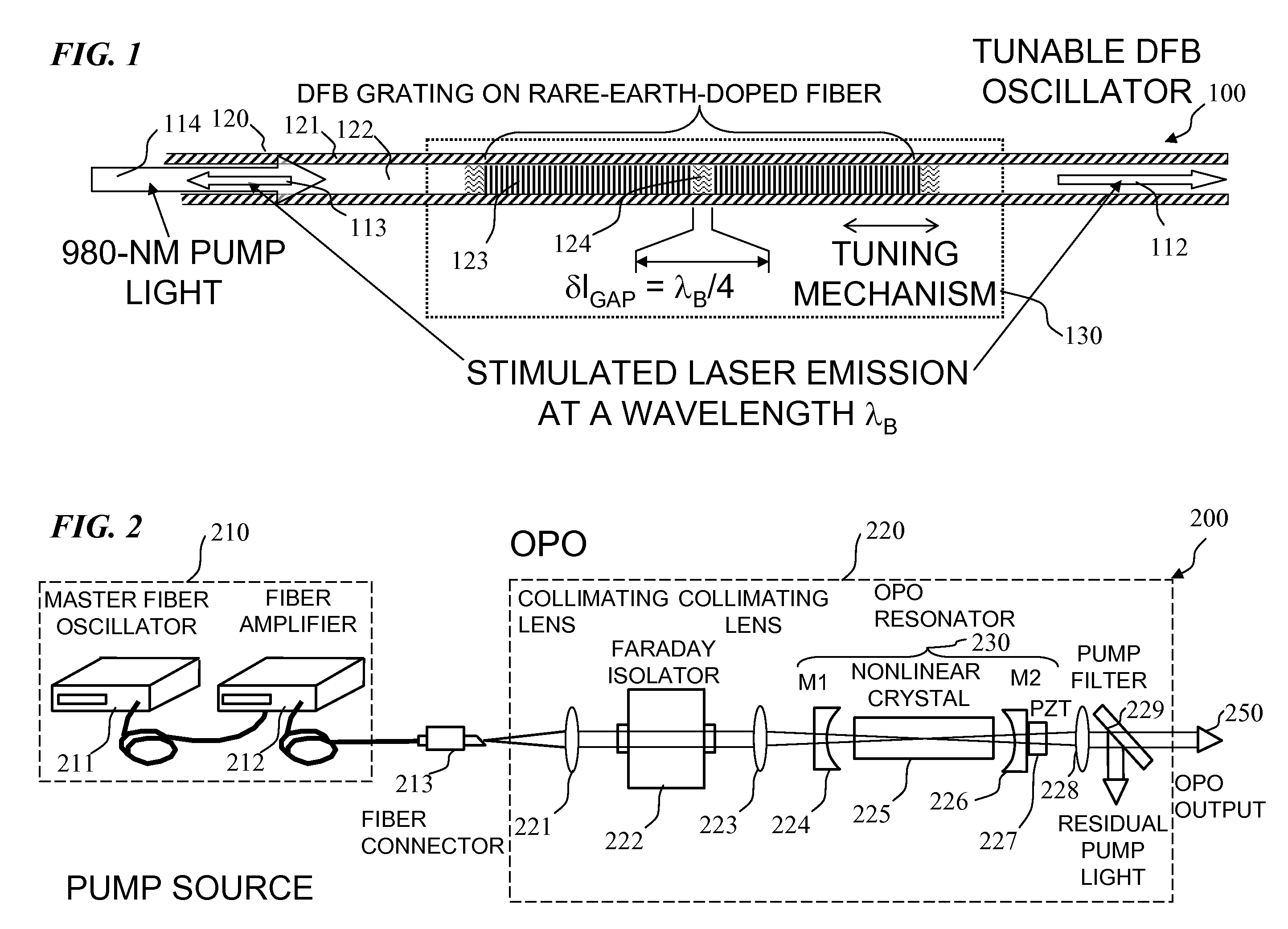
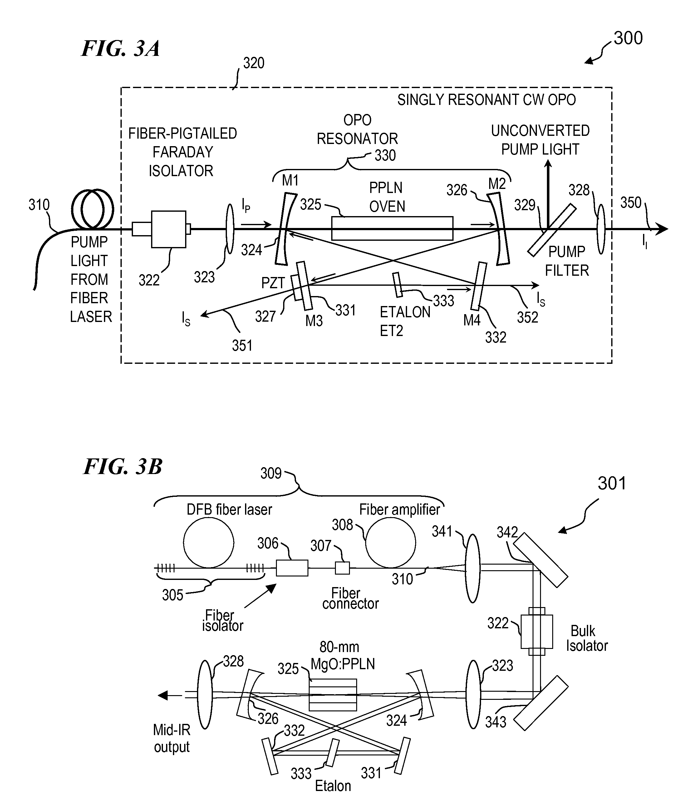
[0010]In some embodiments, the OPO is configured in a bow-tie arrangement having its four mirrors highly reflective (e.g., 99.9% reflectivity) at the resonant wavelength (e.g., the OPO is resonant at the signal wavelength if the idler wavelength is the primary output signal, or the OPO is resonant at the idler wavelength if the signal wavelength is the primary output signal), in order to reduce the threshold pump power needed to obtain and sustain optical-parametric oscillation. In some embodiments, such a configuration causes a very large and undesirable buildup of power circulating within the OPO, particularly at the resonant wavelength (e.g., at the signal wavelength, if that is the resonant wavelength), which causes undesirable heating, particularly of the non-linear element (e.g., Mg:O-doped PPLN (magnesium-oxide-doped periodically-poled lithium niobate), in some embodiments). For example, a reasonably efficient embodiment can achieve 60% to 80% of the pump power converted to signal and idler wavelengths, and if only 0.1% of the resonant wavelength is lost (e.g., absorbed or transmitted) at each of the four mirrors, the OPO cavity pumped with only 15 watts of pump power can build up to a kilowatt or more of circulating power at the resonant wavelength (e.g., the signal wavelength, if that is the resonant wavelength, while three to four watts of idler-wavelength light is output). Even if only a very small percentage of the 1.0-kW signal wavelength is absorbed in the non-linear element, that absorbed power can be several watts, which can cause significant heating of the non-linear element and introduce undesirable non-linear effects such as Ramon scattering and / or other broadening of the output-wavelength signal.
[0012]In some embodiments, the oscillation threshold is adjusted (typically increased for high pump powers) such that the operating pump power is at 2.5 times the oscillation threshold, in order to achieve relatively high conversion efficiency and simultaneously relatively low undesirable non-linear effects, such as Ramon shifting of the output wavelength.
[0019]In some embodiments, the invention provides a method that includes providing an OPO resonator, and stabilizing the OPO output amplitude by servo-controlling the OPO resonator's length to maintain resonance of the OPO resonator on a specific longitudinal mode of pump, signal and / or idler wavelength.

Problems solved by technology

In some embodiments, such a configuration causes a very large and undesirable buildup of power circulating within the OPO, particularly at the resonant wavelength (e.g., at the signal wavelength, if that is the resonant wavelength), which causes undesirable heating, particularly of the non-linear element (e.g., Mg:O-doped PPLN (magnesium-oxide-doped periodically-poled lithium niobate), in some embodiments).
Even if only a very small percentage of the 1.0-kW signal wavelength is absorbed in the non-linear element, that absorbed power can be several watts, which can cause significant heating of the non-linear element and introduce undesirable non-linear effects such as Ramon scattering and / or other broadening of the output-wavelength signal.

Method used


Image

  • Method and apparatus for pumping and operating optical parametric oscillators using dfb fiber lasers
  • Method and apparatus for pumping and operating optical parametric oscillators using dfb fiber lasers
  • Method and apparatus for pumping and operating optical parametric oscillators using dfb fiber lasers

Examples


Embodiment Construction

[0045]Although the following detailed description contains many specifics for the purpose of illustration, a person of ordinary skill in the art will appreciate that many variations and alterations to the following details are within the scope of the invention. Accordingly, the following preferred embodiments of the invention is set forth without any loss of generality to, and without imposing limitations upon the claimed invention. Further, in the following detailed description of the preferred embodiments, reference is made to the accompanying drawings that form a part hereof, and in which are shown by way of illustration specific embodiments in which the invention may be practiced. It is understood that other embodiments may be utilized and structural changes may be made without departing from the scope of the present invention.

[0046]The leading digit(s) of reference numbers appearing in the Figures generally corresponds to the Figure number in which that component is first intro...


PUM


Abstract

An optical parametric oscillator (OPO) is described that efficiently converts a near-infrared laser beam to tunable mid-infrared wavelength output. In some embodiments, the OPO includes an optical resonator containing a nonlinear crystal, such as periodically-poled lithium niobate. The OPO is pumped by a continuous-wave fiber-laser source having a low-power oscillator and a high-power amplifier, or using just a power oscillator. The fiber oscillator produces a single-frequency output defined by a distributed-feedback (DFB) structure of the fiber. The DFB-fiber-laser output is amplified to a pump level consistent with exceeding an oscillation threshold in the OPO in which only one of two generated waves (“signal” and “idler”) is resonant within the optical cavity. This pump source provides the capability to tune the DFB fiber laser by straining the fiber (using an attached piezoelectric element or by other means) that allows the OPO to be continuously tuned over substantial ranges, enabling rapid, wide continuous tuning of the OPO output frequency or frequencies.

Description

CROSS-REFERENCE TO RELATED APPLICATIONS[0001]This is a divisional application of U.S. patent application Ser. No. 11 / 484,358 filed on Jul. 10, 2006 (to issue as U.S. Pat. No. 7,620,077 on Nov. 17, 2009), which claimed priority to U.S. Provisional Patent Application No. 60 / 697,787 filed Jul. 8, 2005, each of which is hereby incorporated herein in its entirety by reference.STATEMENT REGARDING FEDERALLY SPONSORED RESEARCH OR DEVELOPMENT[0002]This invention was made with Government support under Contract no. F29601-03-C-0191 awarded by the Air Force Research Laboratory, Kirtland AFB, New Mexico. The Government has certain rights in the invention.FIELD OF THE INVENTION[0003]The invention relates generally to lasers and nonlinear optical-frequency conversion and more particularly to methods and apparatus applicable for optical parametric oscillators.BACKGROUND OF THE INVENTION[0004]Optical parametric oscillators (OPOs) provide an efficient way of converting short-wavelength electromagneti...

Claims


Application Information

Patent Timeline
Patent Type & Authority Applications(United States)
IPC IPC(8): H01S3/09
CPCH01S3/0675H01S3/06754H01S3/105G02F2203/15H01S3/1055G02F1/39H01S3/1053
Inventor HENDERSON, ANGUS J.
Owner LOCKHEED MARTIN ACULIGHT CORP
Learn More