Energy device, method for manufacturing the same, and apparatus including the same

Active Publication Date: 2010-04-08
PANASONIC CORP
View PDF7 Cites 41 Cited by
  • Summary
  • Abstract
  • Description
  • Claims
  • Application Information

AI Technical Summary

Benefits of technology

[0029]Since the energy device of the present invention can absorb the stress generated by the rolling of the electrode body at the connection portion of the electric conductor that is a supporting member and the carbon nanotube, it can prevent the carbon nanotube from peeling from the electric conductor and significantly reduce the possibility of floating and peeling of the carbon nanotube layer, without using the binding material made of, for example, resin.
[0030]Thus, it is possible to suppress the manufacturing cost of the energy device including the carbon nanotube electrode, reduce the rejection rate of the energy device, and improve the long-term reliability of the energy device. Further, since the mechanical and electrical connection between the electric conductor and the carbon nanotube has become strong, large current discharge can be carried out by

Problems solved by technology

In addition, since the carbon nanotube is connected to the current collector that is the substrate, the carbon nanotube electrode is very low in electrical resistance.
However, in the case of forming the energy device having a rolled structure using the current collector having flexibility, the problem arises where a carbon nanotube layer floats or peels.
Therefore, it has been extremely difficult to apply the carbon nanotube electrode to the energy device having the above structure.
Mo

Method used


Image

  • Energy device, method for manufacturing the same, and apparatus including the same
  • Energy device, method for manufacturing the same, and apparatus including the same
  • Energy device, method for manufacturing the same, and apparatus including the same

Examples


example 1

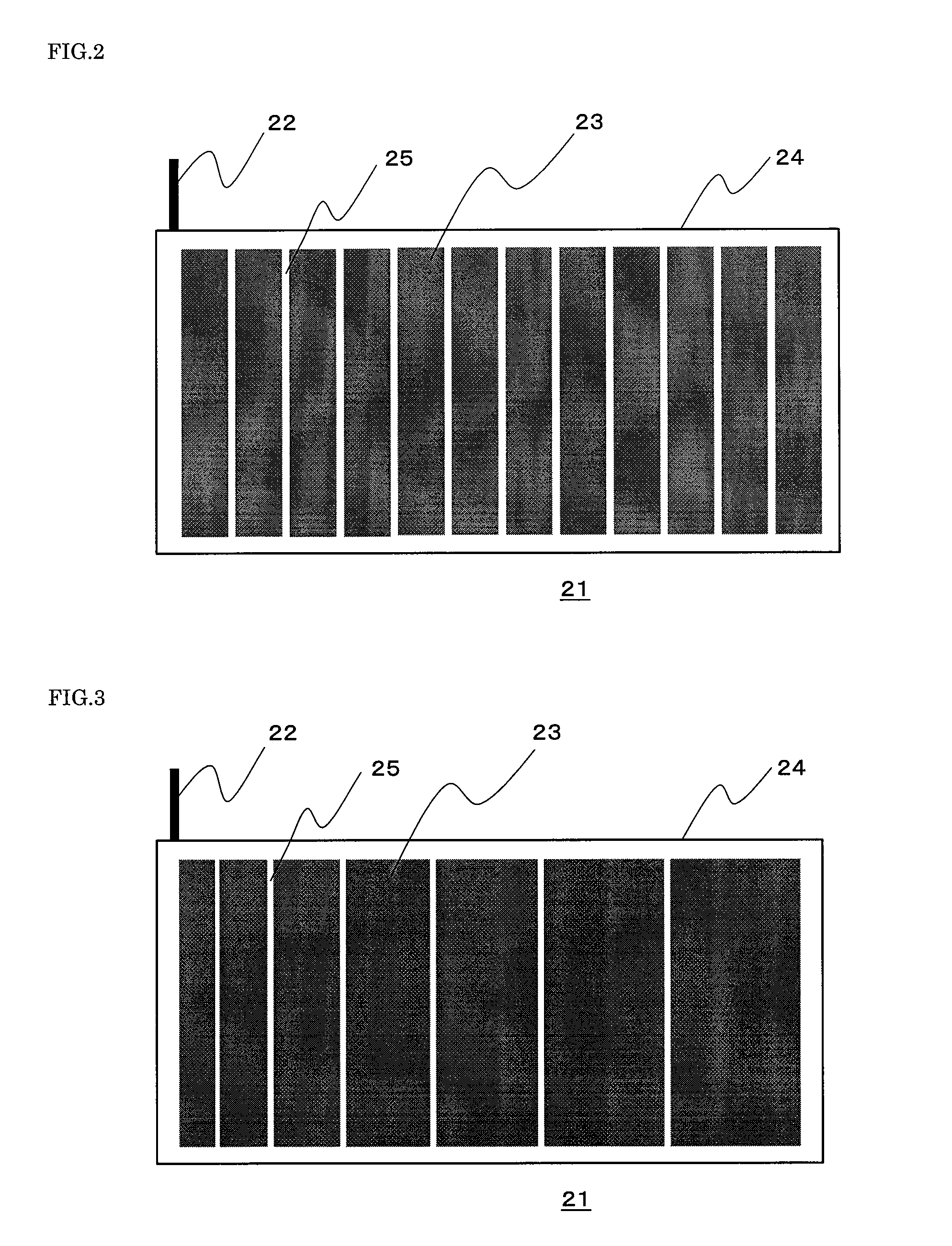
[0066]In a state where a striped patterning mask having a slit width of 4 mm and a slit-to-slit distance of 1 mm covers each of both surfaces of the aluminum foil (thickness of 15 μm) that is the electric conductor, Fe that is the catalyst metal of the carbon nanotube is electron-beam-evaporated on each surface of the aluminum foil so as to have a thickness of 1 nm. Then, the carbon nanotubes are formed on the surfaces of these Fe films, each having a width of 4 mm and formed at intervals of 1 mm, by thermal CVD at 800° C. using methanol as a carbon source. Thus, a bundle of carbon nanotubes each having the width of 4 mm and formed at intervals of 1 mm are vertically formed on both surfaces of the aluminum foil. That is, one end of the bundle is connected to the surface of the aluminum foil.

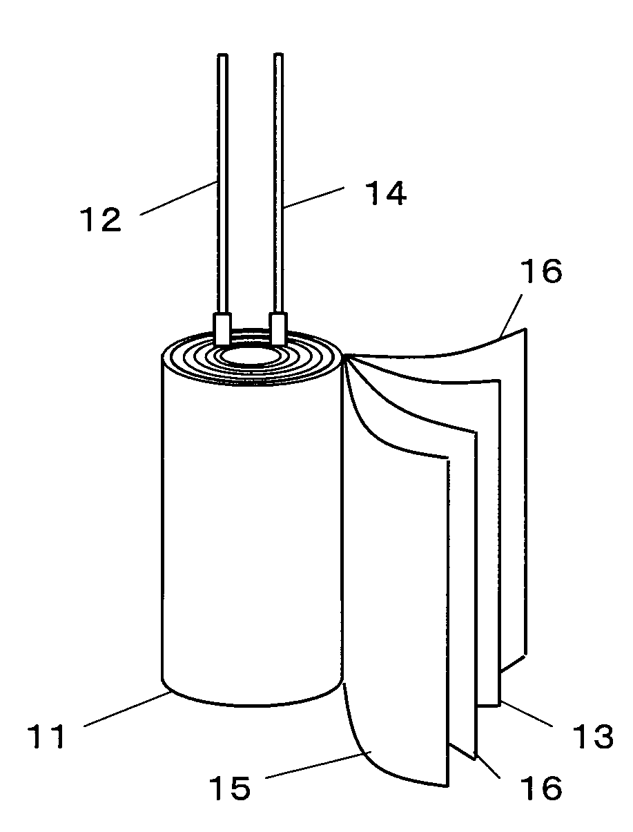
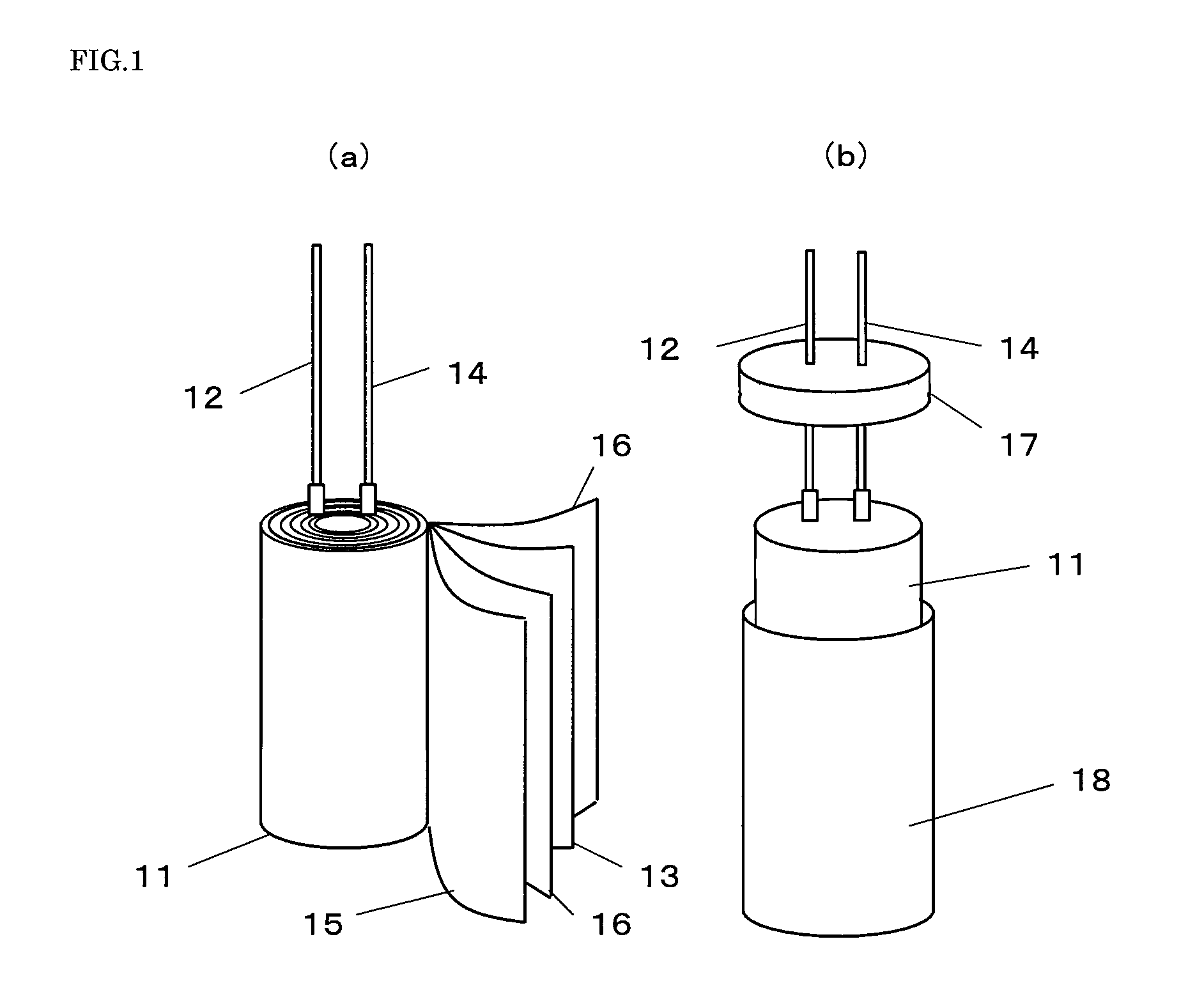
[0067]Then, as shown in FIG. 1, the lead wires are connected to the cathode and the anode, respectively, each formed by the electrode body formed as above. With the separator interposed between t...

example 2

[0068]The electron beam evaporation is carried out without using the patterning mask of Example 1 to form the Fe film having a thickness of 1 nm on the entire surface of the aluminum foil, and the carbon nanotube is formed on the entire surface of the Fe film under the same conditions as Example 1. Then, a part of the carbon nanotube layer is removed by scratching the carbon nanotube layer with the metal wire. Thus, the remaining carbon nanotube layers each has a width of 4 mm and are formed at intervals of 1 mm. Then, the rolled energy device is manufactured in accordance with the same procedure as Example 1. Although the carbon nanotube electrode is visually examined, the peeling and floating of the carbon nanotube layer are not observed.

example 3

[0069]The rolled energy device is manufactured in the same manner as Example 1 except that a patterning mask is used in which the slit width increases by 0.1 mm from 4 up to 8 mm, and the slit-to-slit distance is 1 mm. Although the carbon nanotube electrode is visually examined, the peeling and floating of the carbon nanotube layer are not observed.


PUM

PropertyMeasurementUnit
Electrical conductoraaaaaaaaaa
Distanceaaaaaaaaaa
Electric propertiesaaaaaaaaaa

Abstract

The present invention provides an energy device including a carbon nanotube electrode which prevents a carbon nanotube from peeling from an electric conductor. The energy device includes rolled electrode bodies, wherein at least one of the electrode bodies is formed such that a carbon nanotube layer is formed on the electric conductor, and concave regions are formed in a stripe shape on the carbon nanotube layer so as to extend in a direction parallel to a roll axis.

Description

TECHNICAL FIELD[0001]The present invention relates to an energy device, a method for manufacturing the energy device, and an apparatus including the energy device.BACKGROUND ART[0002]Two main types of the energy device are an energy storage device and an energy generating device. Typical examples of the energy storage device are an electrochemical capacitor and a battery, which have already been used in their appropriate markets. Examples of the electrochemical capacitor are: an electric double layer capacitor which uses an activated carbon as a polarizable electrode and utilizes only an electric double layer formed at an interface between a pore surface of the activated carbon and an electrolytic solution; and a redox capacitor which uses a transition metal oxide, such as ruthenium nitrate, whose valence continuously changes, and an electrically-conductive polymer which can be doped. Moreover, two main types of the battery are: a secondary battery which can be charged and discharge...

Claims


Application Information

Patent Timeline
IPC IPC(8): H01M6/10H01G11/26H01G11/36H01M4/04H01M4/133H01M4/1393H01M4/58H01M4/583H01M4/587H01M10/0525H01M10/0587
CPCH01G9/0029Y10T29/49115H01M4/0428H01M4/133H01M4/1393H01M4/583H01M4/587H01M4/62H01M4/661H01M4/667H01M10/0525H01M10/0587Y02E60/122H01G11/26Y02E60/13H01G11/36Y02E60/10Y02P70/50
Inventor ASARI, TAKUMAYOKOGAWA, TOSHIYAHAYASHI, SHIGEOHASHIMOTO, YASUHIROKUMAGAI, HIRONORI
Owner PANASONIC CORP
Why Eureka
Try Eureka