
Microbial fuel cell with improved anode

a fuel cell and microorganism technology, applied in the field of microorganism fuel cells, can solve the problems of low degree of efficiency in electrical power output, inability to operate efficiently, and inability to improve the efficiency so as to reduce the electrical resistance of microbial fuel cells, improve the efficiency of operation, and improve the effect of electrical power outpu

Active Publication Date: 2010-04-15
UT BATTELLE LLC
View PDF11 Cites 18 Cited by
  • Summary
  • Abstract
  • Description
  • Claims
  • Application Information

AI Technical Summary

Benefits of technology

The present invention provides a method for improving the efficiency and reducing power fluctuations of a microbial fuel cell (MFC) by enriching the biofilm of microorganisms on the anode with exoelectrogenic microorganisms capable of direct electron transfer to the anode. This is achieved by subjecting the microorganisms to a growth stage by incorporating carbon-containing nutritive compounds in the anodic liquid medium. The resulting MFC has improved electrical efficiency and reduced power fluctuations. Additionally, the method includes a process to enrich the biofilm microorganisms with microorganisms capable of storing carbon internally, which further improves the MFC's ability to produce electricity even when feed concentrations are low. Overall, this method provides a more efficient and reliable MFC with minimal power fluctuations.

Problems solved by technology

Furthermore, MFCs can be fueled by waste products (e.g., waste water from sewage treatment or industrial waste), which are typically valueless and in need of degradation.
One problem is that the exoelectrogenic microorganisms being used at the anode represent a small portion of the total amount of microorganisms operating at the anode.
Another problem is that, typically, a significant portion of those microorganisms that operate by an exoelectrogenic mechanism do so by the indirect donation of electrons to one or more mediators.
Both the low concentration of exoelectrogenic microorganisms and the low proportion of exoelectrogenic microorganisms which can operate by a direct electron transfer mechanism are factors that contribute to a low degree of efficiency in electrical power output.
In addition, mediators are often expensive, toxic, and require regular replenishment.
Another problem with current MFCs is the occurrence of electrical power fluctuations.
Such fluctuations are detrimental to the commercial production of electricity.

Method used


Image

  • Microbial fuel cell with improved anode
  • Microbial fuel cell with improved anode
  • Microbial fuel cell with improved anode

Examples


example 1

General Procedure

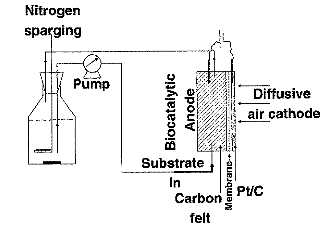
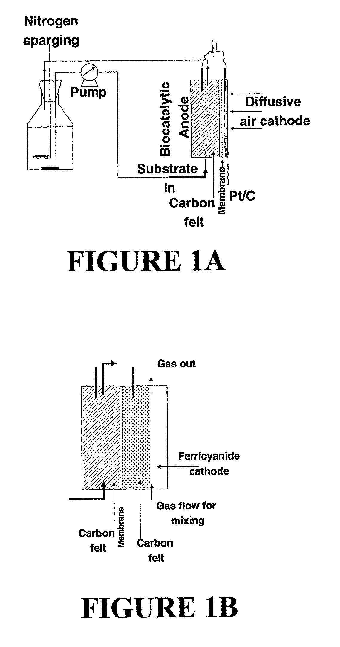
[0080]The enrichment strategy selected for the development of a biofilm-forming exoelectrogenic biocatalyst was a combination of improved anode design and specific operating modes. The features of the design included: a compact anode with negligible electrode spacing, a high anode electrode surface to volume ratio and a flow-through design with forced flow to enable removal of planktonic cells (FIG. 1). The features of the operating modes were as follows: mode I: growth with electrode as the sole electron acceptor, mode II: carbon starvation mode and, mode III: step-wise reduction of external load.

[0081]A compact anode filled with carbon felt with minimal dead volume (i.e., a volume ratio of nearly 1) provided a high surface area for exoelectrogen growth. A flow-through design allowed easy removal of non-biofilm forming organisms via periodic replenishment of the anodic fluid. A forced flow-through anode enabled removal of mediators and organisms attached to the bio...

example 2

Microbial Fuel Cell Construction

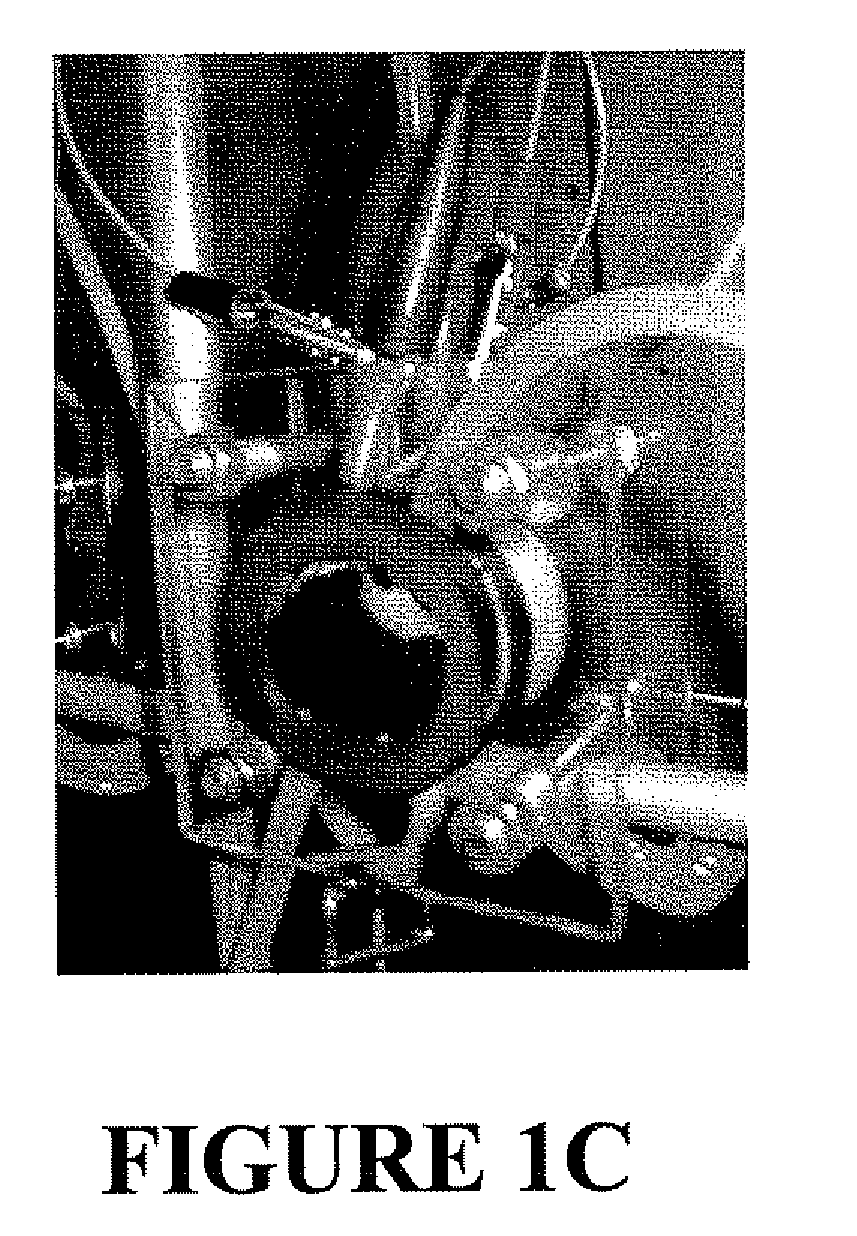
[0087]The MFC used in this study consisted of an anode chamber (4 cm diameter×1.27 cm thickness) containing carbon felt as the electrode material and a platinum-coated carbon as the cathode (Pt / C air-cathode) separated by a Nafion-115 membrane (FIG. 1A). The MFC chamber was made up of a 4 cm diameter PVC pipe, enclosed within two Lexan end plates, bolted together with metal bolts. The liquid flow through the anode was directed upwards through the carbon felt. A gold wire was used as a current collector for the air-cathode and a graphite rod was used for the anode. The Pt / C air-cathode was used during biocatalyst enrichment, while a ferricyanide-cathode (FIGS. 1B, C) was used for determining the maximum power density. The electrode for the ferricyanide cathode was also made using a pipe (4 cm diameter×2.54 cm thick) with carbon felt as the electrode material (2.54 cm×2.54 cm×0.625 cm). The felt was suspended by a carbon rod in a way that the felt surfa...

example 3

Establishment of a Biofilm on the Anode

[0088]The nutrient medium (Medium AC-1) used for enrichment consisted of 975 mL of a sterile mineral solution and 12.5 mL, each of filter sterilized Wolfe's mineral solution and vitamin solution (Gorby, Y. A., et al., PNAS, 103, 11358-11363 (2006)). The mineral solution was made up of 0.31 g NH4Cl, 0.13 g KCl, 4.97 g NaH2PO4.H20 and 2.75 g Na2HPO4.H20 per liter of nanopure water (see, for example, Liu, H. et al., Environ. Sci. Technol., 38, 4040-4046 (2004)), which was adjusted to a pH of 7.0 with 1N NaOH prior to sterilization. The nutrient medium AC-1 (200 ml) was placed in a glass bottle reservoir. (anode liquid reservoir) and recirculated through the anode chamber at 4-7 mL / min (FIG. 1A). The medium was deaerated with nitrogen to remove the dissolved oxygen.

[0089]The anode chamber of the MFCs was inoculated with a 1 mL sample of anaerobic digester slurry collected from a Knoxville municipal wastewater treatment plant. The inoculum was added...


PUM

PropertyMeasurementUnit
flow rateaaaaaaaaaa
flow rateaaaaaaaaaa
flow rateaaaaaaaaaa

Abstract

The present invention relates to a method for preparing a microbial fuel cell, wherein the method includes: (i) inoculating an anodic liquid medium in contact with an anode of the microbial fuel cell with one or more types of microorganisms capable of functioning by an exoelectrogenic mechanism; (ii) establishing a biofilm of the microorganisms on and / or within the anode along with a substantial absence of planktonic forms of the microorganisms by substantial removal of the planktonic microorganisms during forced flow and recirculation conditions of the anodic liquid medium; and (iii) subjecting the microorganisms of the biofilm to a growth stage by incorporating one or more carbon-containing nutritive compounds in the anodic liquid medium during biofilm formation or after biofilm formation on the anode has been established.

Description

[0001]This invention was made with government support under Contract Number DE-AC05-00OR22725 between the United States Department of Energy and UT-Battelle, LLC. The U.S. government has certain rights in this invention.FIELD OF THE INVENTION[0002]The present invention relates to the field of microbial fuel cells, and more specifically, to mediator-less microbial fuel cells.BACKGROUND OF THE INVENTION[0003]Microbial fuel cells (MFCs) are fuel cells which operate by using microorganisms that possess the ability to donate electrons to the anode of the fuel cell in order to produce electricity. Such microorganisms are known as exoelectrogenic organisms. Exoelectrogenic organisms can donate electrons to the anode in either of two ways: via mediators (e.g., the numerous dyes used in the art for this purpose) or in the absence of mediators (i.e. a mediator-less MFC).[0004]An MFC contains an anode, a cathode, and a cation-selective permeable material (typically, a membrane) which separates...

Claims


Application Information

Patent Timeline
Patent Type & Authority Applications(United States)
IPC IPC(8): H01M8/16C12N1/38H01M8/04
CPCH01M4/8605Y02E60/527H01M8/16H01M4/92Y02E60/50
Inventor BOROLE, ABHIJEET P.
Owner UT BATTELLE LLC
Learn More