Electromagnetic shield sheet and RFID plate

a technology of electromagnetic shielding and rfid plate, which is applied in the direction of burglar alarm mechanical actuation, applications, instruments, etc., can solve the problems of electromagnetic interference, tremendous loss on an industrial basis, and the failure of electronic circuits in use, so as to achieve high electromagnetic shielding effect, reduce thickness, and reduce weight

Inactive Publication Date: 2010-04-22
ASAHI RUBBER +1
View PDF6 Cites 74 Cited by
  • Summary
  • Abstract
  • Description
  • Claims
  • Application Information

AI Technical Summary

Benefits of technology

[0015]According to the present invention, even in the cases of electromagnetic shield sheets being the same or comparable in the loading ratio of the conductive material to the polymer material, an electromagnetic shield sheet showing a much higher electromagnetic shielding effect than those of conventional electromagnetic shield sheets can be obtained. Therefore, the electromagnetic shield sheet according to the present invention has a shielding effect which can be sufficiently exhibited even when the sheet has a reduced thickness and a reduced weight. Further, the electromagnetic shield sheet of the invention allows additional provision of excellent formability (moldability) and flexibility, so that the sheet can be used in electronic apparatuses of various shapes for electromagnetic shielding. In addition, since the electromagnetic shield sheet has a high shielding effect and a high reflection efficiency, an efficient RFID (Radio Frequency Identification) plate can be realized by laminating the sheet with an antenna circuit, such as a printed antenna circuit, or an IC (Integrated Circuit) with an antenna which is operative to process signals for transmission / reception of an electromagnetic wave.

Problems solved by technology

While on one hand the convenience on a living basis is enhanced by the progress of electronic technologies, on the other hand troubles of failure of electronic circuits in use are generated due to influences of electromagnetic waves coming from the outside or the inside of an apparatus.
For instance, in an electronic circuit board, electromagnetic interference occurs between a reactance circuit on the circuit board and an adjacent semiconductor device or the like.
If this causes a malfunction or halt of a circuit to make an electronic controller's control impossible, a tremendous loss on an industrial basis would result.
In the case of a common consumer, also, such a trouble makes it impossible for the consumer to use the electronic apparatus without anxiety.
However, these shielding materials are insufficient in performance and have shortcomings as to weight (mass) and production cost.
Thus, an electromagnetic shielding material which is light in weight, inexpensive, and sufficient in properties demanded industrially has not been present or put to satisfactory use.
Thus, a satisfactory electromagnetic shielding sheet (electromagnetic shield sheet) cannot easily be supplied at present.
Depending on the mode of use, however, the conductive rubber composition has not necessarily provided a sufficient effect efficiently in precision circuits or the like, due to diffraction of electromagnetic waves or the like.
In this technology, however, the shielding effect is obtained by absorbing the electromagnetic waves coming from the generating source and, therefore, there is a problem in that the sheet generates heat upon absorption of energy, so that the resulting deformation or the like leads to a change in the shielding effect, and the shielding sheet cannot be used stably.
In addition, since a large amount of ceramic is used, an increase in weight results, which is disadvantageous from the viewpoint of convenience for portable electronic apparatuses.
Such an absorber, however, not only has an increased weight but also has the problem that the particles of the spherical magnetic powder contained therein are large.
Therefore, use of the spherical magnetic powder alone would lead to nonuniformity of dispersion.

Method used


Image

  • Electromagnetic shield sheet and RFID plate
  • Electromagnetic shield sheet and RFID plate
  • Electromagnetic shield sheet and RFID plate

Examples


example 1

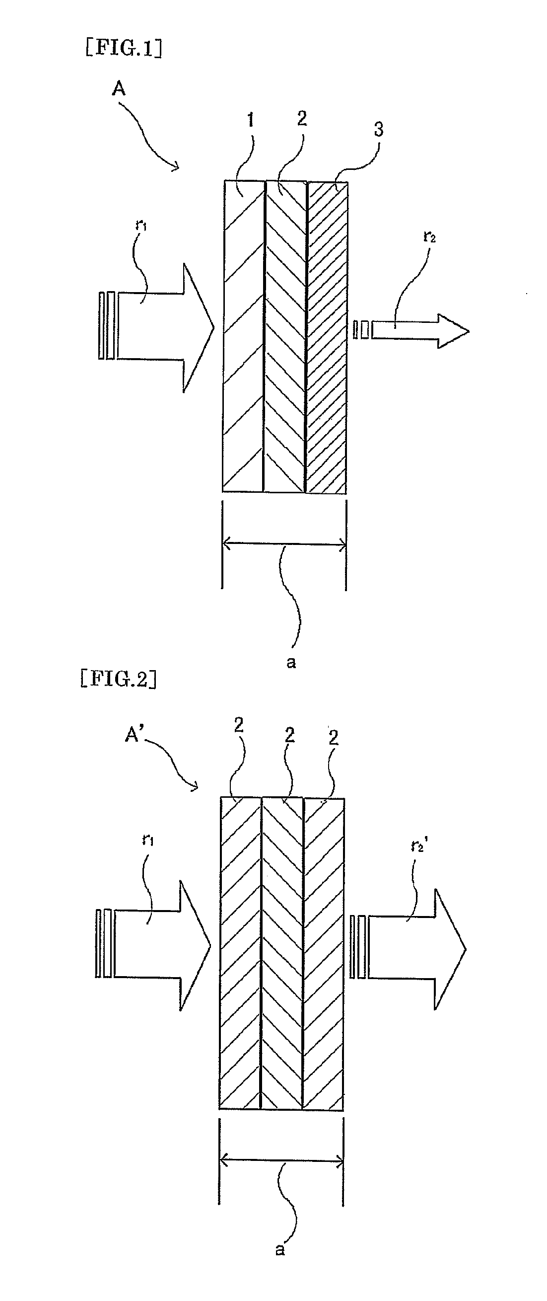
[0057]A silicone rubber (trade name “DY32-152U,” produced by Dow Corning Toray Co., Ltd.) in an amount of 100 parts by weight was kneaded respectively with 5 phr, 10 phr, and 20 phr of carbon fibers (trade name “XN-10C,” produced by Nippon Graphite Fiber Corp.) having a diameter of 10 μm and a length of 3 mm, followed by press molding. As a result, an electromagnetic shield sheet A of Example 1 as shown in FIG. 1 was obtained which had a total thickness (indicated by arrows (a) in the figure) of 3 mm and in which a polymer composition layer 1 having a carbon fiber mixing ratio of 5 phr based on 100 parts by weight of the silicone rubber, a polymer composition layer 2 having a carbon fiber mixing ratio of 10 phr, and a polymer composition layer 3 having a carbon fiber mixing ratio of 20 phr were sequentially and integrally molded, with the thickness of each layer being 1 mm.

example 2

[0058]An electromagnetic shield sheet of Example 2 was obtained in the same manner as in Example 1, except that the molding was so performed that the thickness of each of the polymer composition layers 1, 2, 3 was 0.5 mm and the total thickness of the sheet was 1.5 mm.

example 3

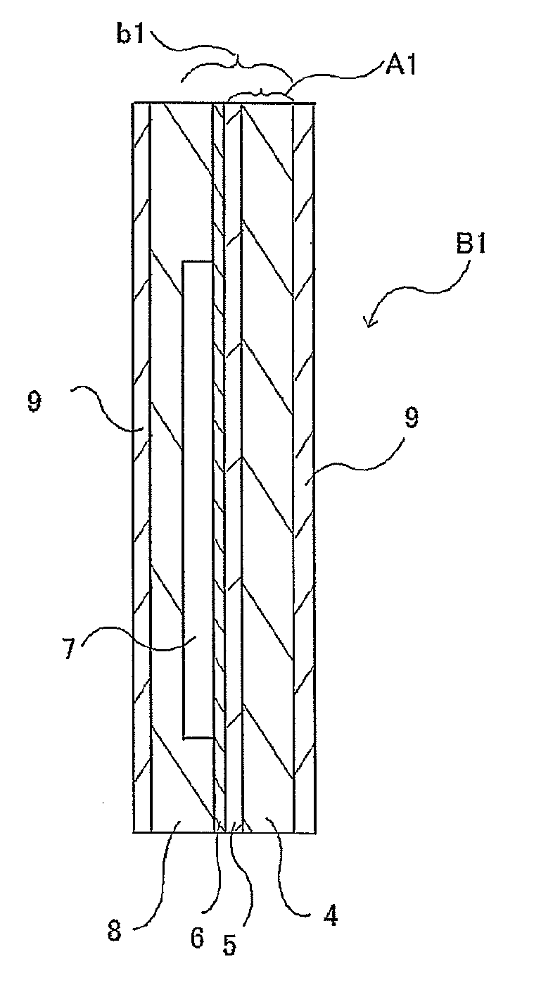
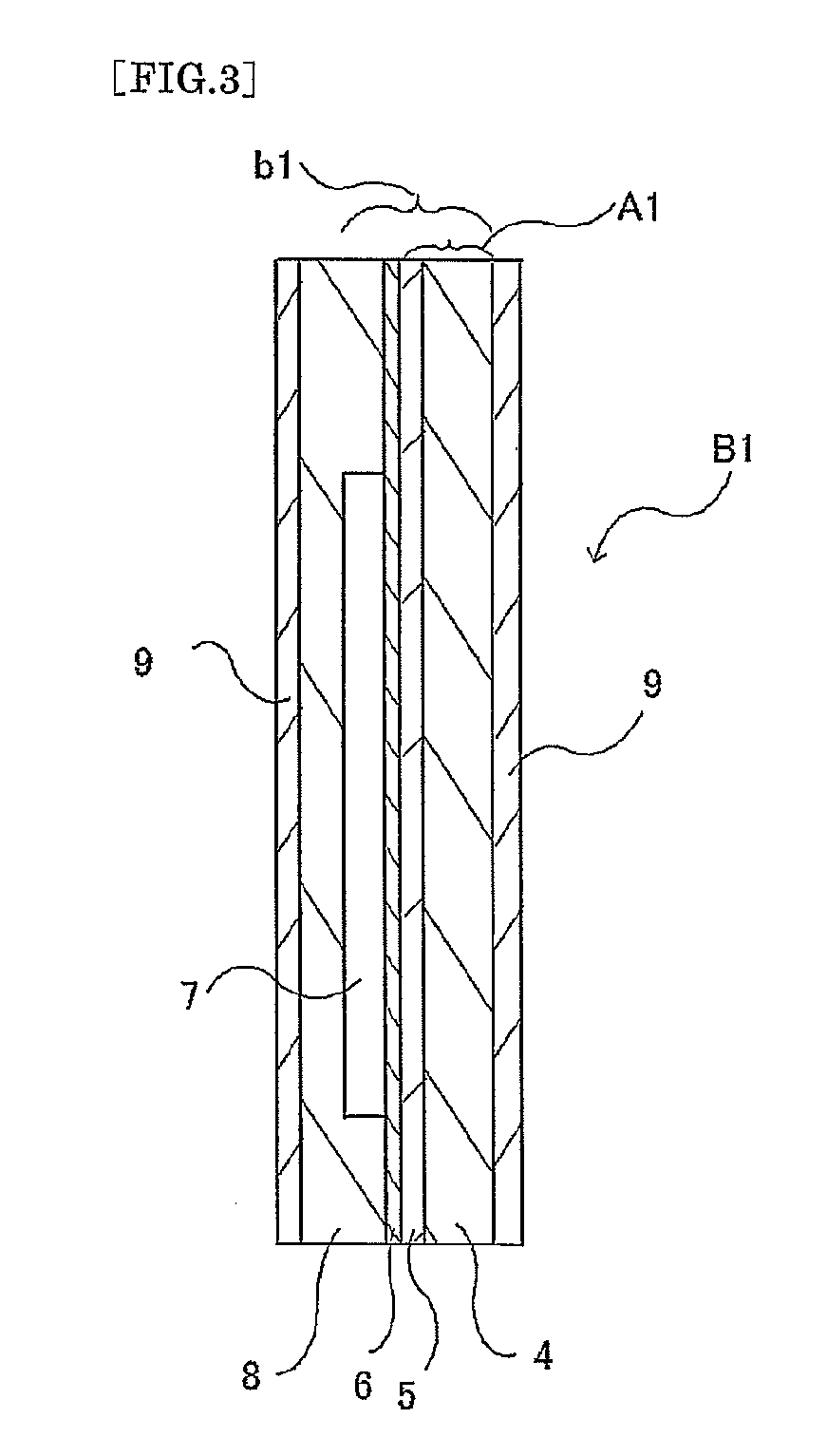
[0064]A transparent silicone rubber layer formed of a silicone rubber (trade name “BY32-152U,” produced by Dow Corning Toray Co., Ltd.) and having a thickness of 1 mm was provided on the side of the polymer composition layer 1 containing 5 phr of the carbon fibers of the electromagnetic shield sheet of Example 1, at the time of integral molding. The transparent silicone rubber layer was subjected to a corona discharge treatment, and was thinly coated with a silicone pressure sensitive adhesive layer (trade name “KE4805,” produced by Shin-Etsu Chemical Co., Ltd.), to obtain a pressure sensitive adhesive electromagnetic shield sheet as electromagnetic shield sheet of Example 3. Two such sheets were prepared, and were adhered respectively to the face and back sides of an electronic circuit board with circuit elements arranged therein, by utilizing the pressure sensitive adhesive layers, to obtain a circuit board protected from electromagnetic waves. The electromagnetic shield sheets wo...


PUM

PropertyMeasurementUnit
particle diameteraaaaaaaaaa
diameteraaaaaaaaaa

Abstract

Provided is an electromagnetic shield sheet having an excellent electromagnetic shielding effect which can be sufficiently exhibited even when the sheet has a reduced thickness and a reduced weight. Furthermore, the electromagnetic shield sheet has an excellent molding efficiency and flexibility and can be used in a desired shape such as various shapes of a power supply box, an inner wall, or an electronic device for electromagnetic shielding. An RFID plate using the electromagnetic shield sheet is also provided. The electromagnetic shield sheet A has a polymer composition layer obtained by mixing a conductive material with a polymer material. The sheet A is formed by layering at least two of polymer composition layers 1, 2, 3 having different dielectric constants. The RFID plate is formed by layering the electromagnetic shield sheet A, an IC, and an antenna circuit.

Description

TECHNICAL FIELD[0001]The present invention relates to an electromagnetic shield sheet which can shield electromagnetic waves propagated toward an electronic apparatus from external environments or electromagnetic waves leaking from the inside of an electronic apparatus or can shield electromagnetic waves with respect to only a space spreading in some direction(s). More particularly, the invention relates to an electromagnetic shield sheet having an excellent electromagnetic shielding effect which can be sufficiently exhibited even when the sheet has a reduced thickness and a reduced weight. In addition, the invention relates to an electromagnetic shield sheet which can cope with a variety of shapes and which also allows addition of heat resistance, dimensional stability, and radiating properties in relation to heat. The invention relates to an electromagnetic shield sheet which, when obtained by layering at least two polymer composition layers having different dielectric constants, ...

Claims


Application Information

Patent Timeline
Patent Type & Authority Applications(United States)
IPC IPC(8): H05K9/00G08B13/14B32B7/025
CPCB32B7/02H05K9/0088B32B25/08B32B25/20B32B27/08B32B27/18B32B2262/106B32B2264/10B32B2264/107B32B2307/202B32B2307/206B32B2307/212B32B2457/00B32B2457/08B32B2519/02H05K9/0083B32B25/042B32B7/12B32B2307/302B32B2307/306B32B2307/3065B32B2307/41B32B2307/734B32B2425/00B32B7/025
Inventor NAKAMURA, MUNETOMOKOYAMASHITA, YUJI
Owner ASAHI RUBBER
Why Eureka
Try Eureka