Method And Circuitry for Improving the Magnitude and Shape of the Output Current of Switching Power Converters

a technology of output current and magnitude, applied in the direction of electric variable regulation, process and machine control, instruments, etc., can solve the problems of system malfunction, severe damage to feeding sources, and limited mode of operation, so as to reduce power and stress of said switches

Inactive Publication Date: 2010-04-22
BEN GURION UNIVERSITY OF THE NEGEV
View PDF11 Cites 26 Cited by
  • Summary
  • Abstract
  • Description
  • Claims
  • Application Information

AI Technical Summary

Benefits of technology

[0023]The present invention is directed to a method and circuitry (apparatus) that behaves as an inherent current source, for injecting a sinusoidal current into a power line. According to an embodiment of the present invention, a current feedback loop is not required for the basic injection operation. In addition, if a current feedback loop is not used, undesired currents will not be injected to the grid, and the circuitry will not be damaged by the grid when the current feedback loop is lost.
[0041]According to still a further embodiment of the present invention, the apparatus further implements soft switching of the switches of the inverter for reducing the power and stresses of said switches.

Problems solved by technology

The latter is due to the fact that current control loops of a voltage source converter are sensitive to deterioration of electrical components, spurious signals, noise and the like.
Once the current loop is lost, the system may not only malfunction but could be severely damaged when the voltage sourcing converter is connected to a load which behaves like a voltage source.
This mode of operation is rather limited in that it does not contribute to the general electrical energy needs.
When the alternative energy source is unavailable, the power line can still feed all loads connected to it.
The latter not only constitutes a malfunction, but may cause severe damage to the feeding source.
Another issue that needs to be carefully taken care of is the requirement of feeding the power line with a current of low harmonics content.
This requirement is mandatory since the injection of high harmonic current is harmful; it increases power losses and could generate voltage interferences that might disturb other customers of the power line.
However, since the impedance of this inductor to the line frequency (50 Hz or 60 Hz depending on country) is very small, any voltage deviations between a Voltage Source 101 and a Power Line 106 will cause large uncontrolled current.
Even so, the reliability of such a system is low, since a loss of the current feedback, due to noise or failure of components will be catastrophic.
Furthermore, the inclusion of a feedback loop may cause dynamic instability and will add to the cost of the system.
Also, the teaching of U.S. Pat. No. 7,084,584 does not cover the issue of maximum power point tracking (MPPT) as is required in the case of alternative energy sources.
The shortcomings of the circuit presented on FIG. 5, as a source for a grid-connected system, are: poor utilization of the magnetic element; high voltage stresses on the primary switch; voltage spikes associated with the parasitic inductance of the coupled inductor; the pulsating current at the output; and low energy levels that can be processed by a flyback stage at reasonable losses.
However, the system of FIG. 7 does not generate a sinusoidal current, synchronized to the power line voltage, as is required for the grid (power line) connected source.

Method used


Image

  • Method And Circuitry for Improving the Magnitude and Shape of the Output Current of Switching Power Converters
  • Method And Circuitry for Improving the Magnitude and Shape of the Output Current of Switching Power Converters
  • Method And Circuitry for Improving the Magnitude and Shape of the Output Current of Switching Power Converters

Examples


Embodiment Construction

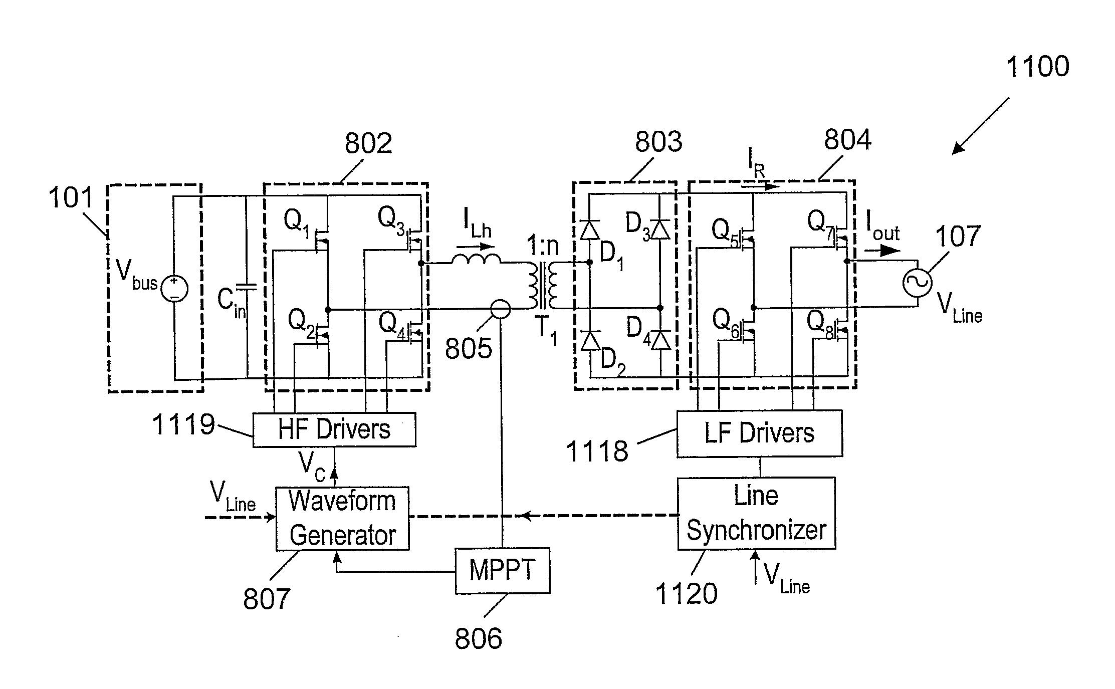
[0068]The present invention is directed to a method and circuitry (apparatus) that behaves as an inherent current source, for injecting a sinusoidal current into a power line.

[0069]FIG. 8 is a schematic block diagram 800 of a of a circuitry (apparatus) of a grid-connected inverter for injecting a current into a Power Line 107, according to an embodiment of the present invention. The circuitry of the grid (Power Line 107) connected inverter comprises: an Electrical Energy Source 101 for providing the substantially DC voltage to said circuitry; an Inverter 802 for converting said substantially DC voltage of said Electrical Energy Source 801 to a high frequency alternating voltage Vinv; a Waveform Generator 807 for controlling said high frequency alternating voltage Vinv by means of a control signal Vc fed into said Inverter 802; an inductor Lh connected in series to an output of said Inverter 802 for generating an alternating current ILh due to the high frequency alternating voltage V...


PUM


Abstract

Apparatus of a grid-connected switching inverter for injecting it current into a power line comprises: (a) an electrical energy source for providing the substantially DC voltage to the apparatus; (b) a switching inverter connected to the electrical energy source for converting the substantially DC voltage of the electrical energy source to a high frequency alternating voltage; (c) a waveform generator for controlling the magnitude and shape of the alternating high frequency voltage outputted from the switching inverter by means of a control signal fed into the switching inverter; (d) an inductor connected to an output of the switching inverter for generating an alternating current from the alternating high frequency voltage, wherein the magnitude of the alternating current depends on a frequency of the alternating high frequency voltage: (e) a rectifier connected in series with the inductor for rectifying the alternating current and for outputting a rectified unipolar alternating current, wherein the rectified average value of the alternating current is proportional to the absolute magnitude of the power line voltage; and (t) a polarity commutator connected to an output of the rectifier for converting the rectified unipolar alternating current into a bipolar alternating current, and for injecting the bipolar alternating current into a power line, wherein the bipolar alternating current is substantially in phase with and of shape of the power line voltage of the power line.

Description

FIELD OF THE INVENTION[0001]The present invention relates to switching power converters. More particularly, the invention relates to a method and circuitry for improving the magnitude and shape of the output current of switching power converters.BACKGROUND OF THE INVENTION[0002]Currently, there are several types of power converters which are widely used for the DC-to-DC (Direct Current), DC-to-AC (Alternating current), AC-to-DC and AC-to-AC power conversion. In some applications, the purpose of the converter is to provide a regulated output voltage. In other applications, the purpose of the power conversion scheme is to regulate the output current independent of the load voltage. For example, in the case of a battery charger, the converter needs to feed the battery with a current rather than with a fixed output voltage. Another example is a grid-connected inverter for feeding energy into the power line. In this case, the required shape of the current is a sinusoidal waveform synchro...

Claims


Application Information

Patent Timeline
Patent Type & Authority Applications(United States)
IPC IPC(8): H02M7/5387H02M3/335
CPCH02M2001/007H05B41/2886H05B41/2887Y02B20/202H02J3/387Y02E10/763H02J3/385H02J3/386Y02E10/563Y02E10/58H02J3/383H02J2300/40H02J2300/30H02J2300/28H02J2300/26H02J2300/24H02J3/381Y02B20/00Y02E10/56Y02E10/76H02M1/007H02J3/46H02J3/44
Inventor BEN-YAAKOV, SHMUEL
Owner BEN GURION UNIVERSITY OF THE NEGEV
Why Eureka
Try Eureka