On-board-diagnosis method for an exhaust aftertreatment system and on-board-diagnosis system for an exhaust aftertreatment system

a technology of exhaust aftertreatment and on-board diagnostic system, which is applied in the direction of exhaust treatment electric control, electrical control, machines/engines, etc., can solve the problems of increased nox levels, high nox levels, and only possible high efficiency, and achieve high nox conversion, high nox conversion, and good no2/no ratio

Active Publication Date: 2010-04-29
VOLVO LASTVAGNAR AB
View PDF3 Cites 43 Cited by
  • Summary
  • Abstract
  • Description
  • Claims
  • Application Information

AI Technical Summary

Benefits of technology

[0015]Another advantage with the present invention is that one may achieve high passive regeneration and HC oxidation in the DPF system and maintaining a good NO2 / NO ratio for high NOx-conversion in the SCR-system for a fresh as well as an aged system. Advantageously, the preferred arrangement allows to using a smaller SCR-catalyst, giving both cost, space and weight benefits. The diesel particulate filter unit (DPFU) may have the oxidation catalyst (DOC) upstream of the diesel particulate filter (DPF). Alternatively or additionally, the DPF may comprise a catalytic coating which oxidizes exhaust gas components and which can replace or support the DOC. An advantage with this embodiment is that one will still further save space, cost and weight.

Problems solved by technology

Said high efficiency is however only possible at an elevated combustion temperature at which high NOx levels are inevitable.
Moreover, a suppression of NOx formation by internal means (air / fuel ratio) has the tendency to cause an increase in particulates, known as the NOx -particulates trade off.
Furthermore, an excess of oxygen in the exhaust gas from a diesel engine prevents the use of stoichiometric 3-way-catalyst technology for reduction of NOx as, is used in gasoline engine oars from the late 80-ties.
This degradation seriously influences the operation of aftertreatment systems.

Method used


Image

  • On-board-diagnosis method for an exhaust aftertreatment system and on-board-diagnosis system for an exhaust aftertreatment system
  • On-board-diagnosis method for an exhaust aftertreatment system and on-board-diagnosis system for an exhaust aftertreatment system
  • On-board-diagnosis method for an exhaust aftertreatment system and on-board-diagnosis system for an exhaust aftertreatment system

Examples


Embodiment Construction

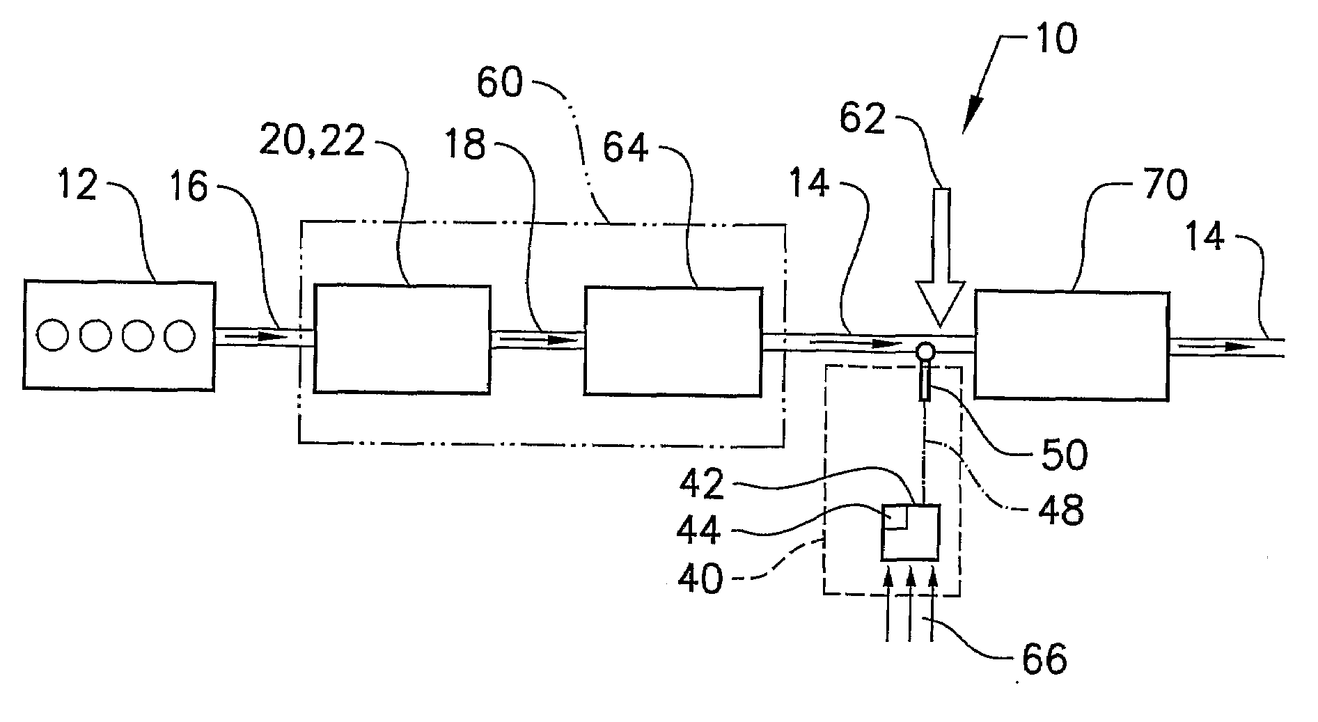
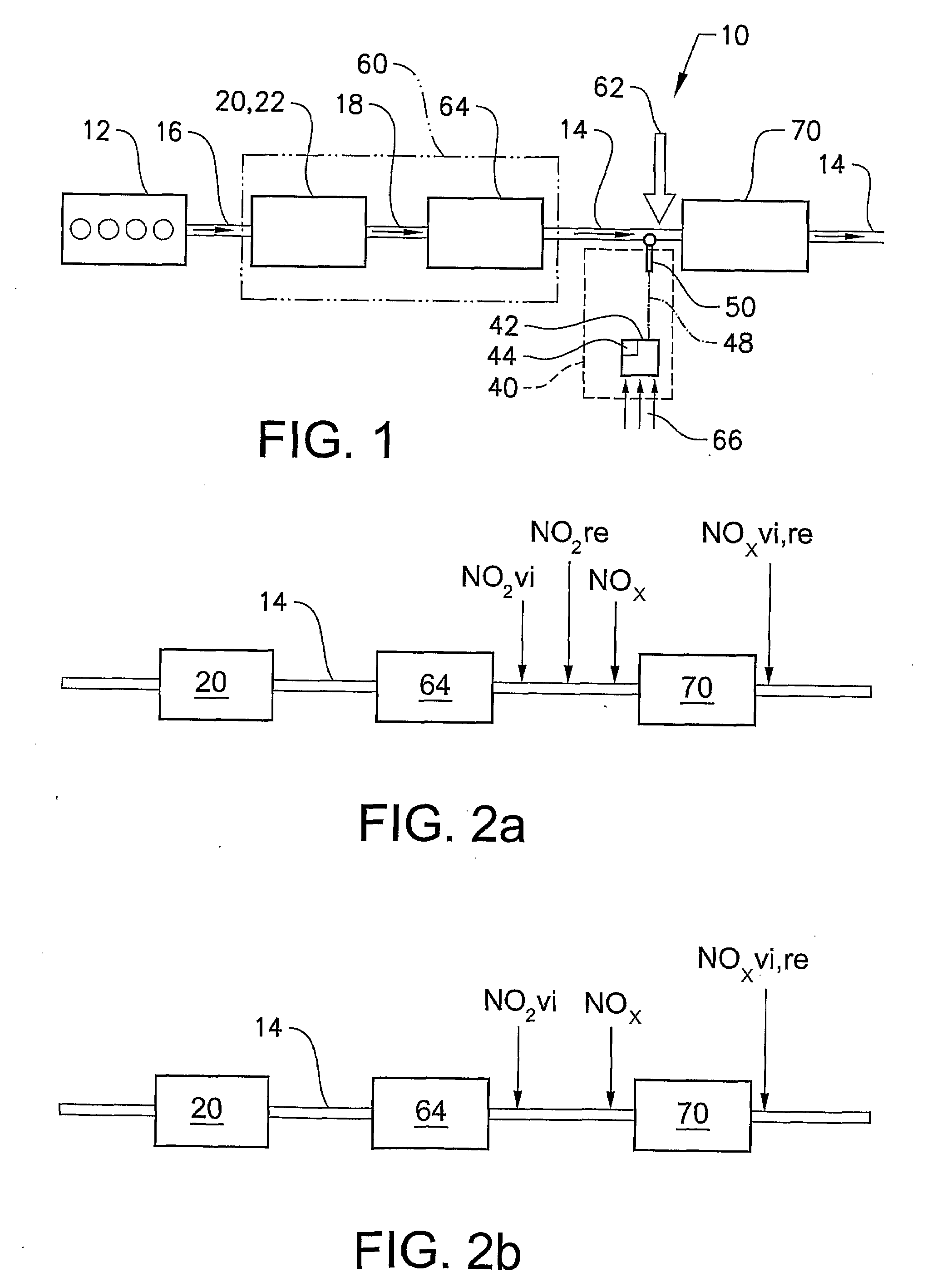
[0032]According to a first aspect of the invention a preferred exhaust gas after treatment system 12 depicted in FIG. 1 comprises a diesel particulate filter unit (DPFU) 60 arranged downstream of a diesel engine 12 and a NOx reducing unit 70 such as preferably a selective-catalytic-reduction (SCR) arrangement arranged downstream of said DPFU 60, wherein an injector 62 is provided for feeding reducing agent such as ammonia or urea into the exhaust gas and arranged downstream of said DPF 64 and upstream said SCR catalyst. The DPFU 60 comprises an oxidation catalyst stage (DOCS) 20, e.g. an oxidation catalyst (DOC) 22 and a diesel particulate filter unit (DPFU) 60 which is arranged downstream of the DOC 22. Optionally, the DPF 64 can exhibit an oxidizing catalytic coating which can replace the DOC 22 as oxidation stage 20 or which can at least support the DOC 22.

[0033]Between the DPFU 60 and the SCR catalyst a sensing unit 40 is provided for sensing the amount of NO2 contained in the e...


PUM


Abstract

A system and an on-board-diagnosis method is provided for an exhaust aftertreatment system of an engine including a diesel particulate filter unit which encompasses a particulate filter in which soot can be oxidized by NO2 and constituents of the exhaust gas are deoxidized in a nitrogen-oxides reduction unit arranged downstream of the diesel particulate filter unit, wherein the exhaust gas flows from the diesel particulate filter unit to the nitrogen-oxides reduction unit. The on-board-diagnosis method includes estimating an NO2 content upstream of the nitrogen-oxides reduction unit, measuring at least one of an NOx or NO2 content upstream of the nitrogen-oxides reduction unit, performing a comparison between the estimated and the measured contents, and, based on the result of the comparison deciding on at least one conditioning step of the diesel particulate filter unit.

Description

BACKGROUND AND SUMMARY[0001]The invention relates to an on-board-diagnosis method for an exhaust aftertreatment system and an on-board-diagnosis system for an exhaust aftertreatment system.[0002]Present regulatory conditions in the automotive market have led to an increasing demand to improve fuel economy and reduce emissions in present vehicles. These regulatory conditions must be balanced with the demands of a consumer for high performance and quick response for a vehicle.[0003]A diesel engine has an efficiency of up to about 52% and is thus the best converter of fossil energy. NOx emission concentration, i.e. the emission of nitrogen oxides NO and NO2, is dependent upon local oxygen atom concentration and the local temperature. Said high efficiency is however only possible at an elevated combustion temperature at which high NOx levels are inevitable. Moreover, a suppression of NOx formation by internal means (air / fuel ratio) has the tendency to cause an increase in particulates, ...

Claims


Application Information

Patent Timeline
Patent Type & Authority Applications(United States)
IPC IPC(8): F01N11/00F01N3/035F01N3/10F01N9/00
CPCF01N3/021F01N13/009F01N3/033F01N3/035F01N3/103F01N3/106F01N3/2053F01N3/206F01N3/2066F01N3/208F01N2410/00F01N2430/00F01N2430/08F01N2430/10F01N2510/0682F01N2560/026F01N2560/06F01N2560/14F01N2570/14F01N2610/02F01N2610/03F01N2900/14F01N2900/1402F02D41/1463F02D41/1465F02D41/1467F02D2200/0812Y02T10/24F01N3/0231Y02A50/20Y02T10/12
Inventor TUOMIVAARA, ANDERSJANSSON, JONASMEGAS, LUCASANDERSSON, LENNARTEDVARDSSON, JONASKARLSSON, CARL-JOHAN
Owner VOLVO LASTVAGNAR AB
Why Eureka
Try Eureka