
Reconfigurable Amplifier and Filter Using Time-Varying Circuits

a technology of time-varying circuits and amplifiers, applied in filtering, gain control, frequency selective two-port networks, etc., can solve problems such as the drawbacks of sras that must be overcome to maximize the potential of sras, and achieve the effect of avoiding aliasing, high sampling rate, and high gain

Inactive Publication Date: 2010-05-06
T VAR SEMICON
View PDF6 Cites 3 Cited by
  • Summary
  • Abstract
  • Description
  • Claims
  • Application Information

AI Technical Summary

Benefits of technology

[0021]By using time-varying circuits, sharper filters and greater amplification is achieved while consuming less IC area and power. IC area is reduced because the bandwidth of the filter is not strictly determined by the size of the resistors and capacitors. Instead, the control signals that communicate with the time-varying circuits in each branch of the system provide additional variables that set the filter bandwidth. As a result, smaller capacitors and resistors can be used. Furthermore, a single time varying circuit can achieve much sharper filtering than a single filtering stage in a classical LTI filter. To achieve comparable filtering performance, LTI filters require a cascade of various stages resulting in larger area and power consumption.
[0022]Power consumption in classical LTI filters is largely due to the high-gain op-amps or high output resistance transconductors required. In contrast, time-varying circuits such as analog multipliers and SRAs require minimal gain. In the case of SRAs, required gain is slightly greater than one. This means that each branch of the proposed A&F system consumes considerably less power than an op-amp, and even when N branches are used, the overall system power consumption is reduced.
[0023]Better flexibility and reconfigurability are also achieved in the present invention compared with classical filters and amplifiers. This is because the time-varying circuits in each branch of the system are controlled by synthesized signals that determine the filter response and gain of the overall system. As a result, filtering qualities of the system can be reconfigured by changing the rates at which the system is clocked and the shape of the signals controlling the time-varying circuits.
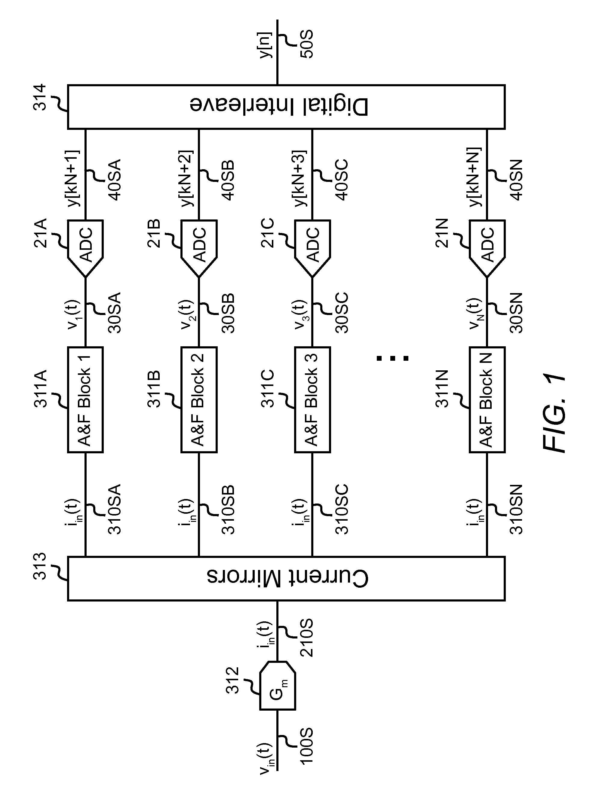
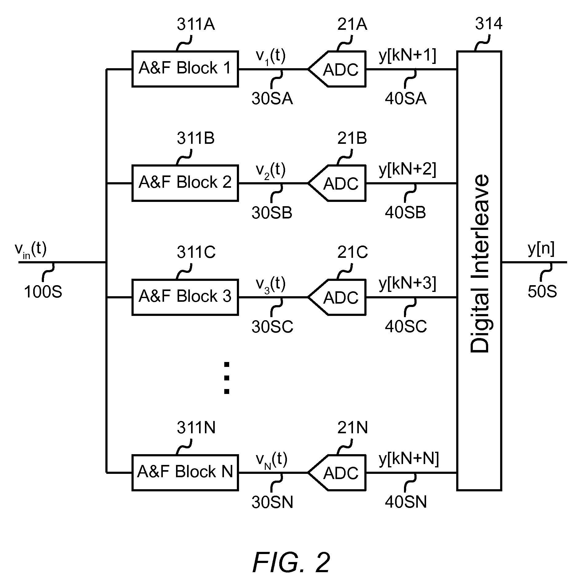
[0026]The first challenge associated with SRAs is overcome by using N parallel branches, each with one SRA. That is to say, in contrast with typical systems using a single SRA, by using N parallel SRAs the strict relationship between sampling rate and SRA bandwidth is broken. This is because the sampling rate is not longer equal to the quench frequency, but rather fs=N×fq, where fq is the quench frequency. By using a high enough number of parallel branches (each with an SRA), the sampling rate can be made high enough to avoid aliasing while using the SRA as its own anti-aliasing filter.
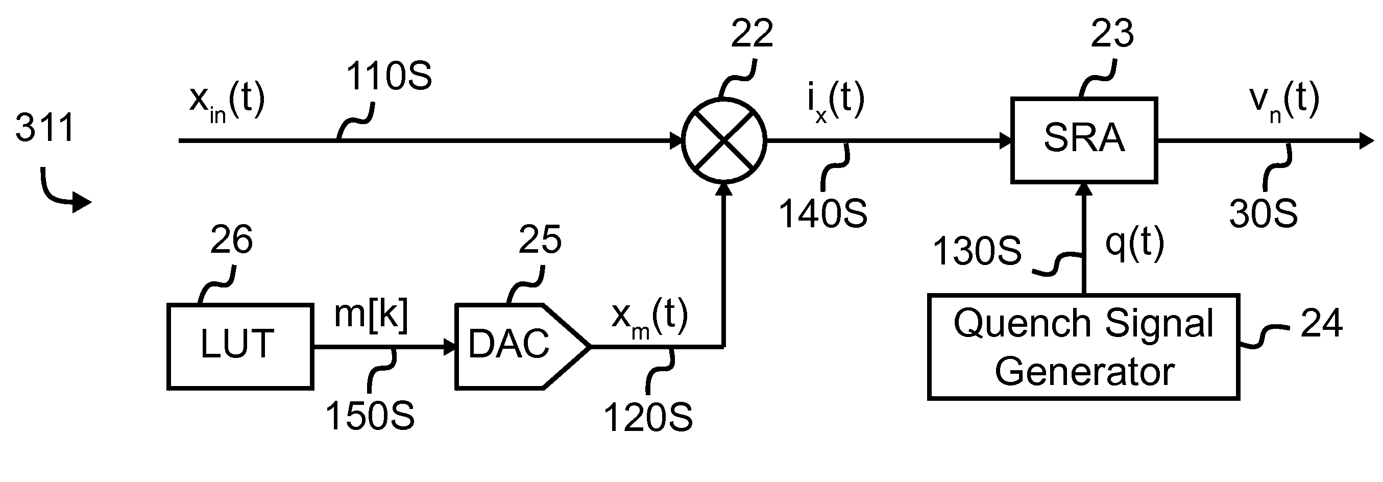
[0027]The second challenge associated with SRAs is the strictly non-negative filter impulse response. In the present invention, this challenge is overcome by preceding each SRA with an analog multiplier. In the most general implementation of the invention, the multiplicand input of the analog multiplier communicates with the input signal and the multiplier input of the multiplier communicates with a multiplier signal synthesized by a digital-to-analog converter (DAC). The output of each analog multiplier communicates with the signal input of the SRA and a quench signal generator communicates with the control input of the SRA in each block. The resulting impulse response of the overall filter is the product of the multiplier signal connected to the analog multiplier and the inherent impulse response of the SRA. Since the multiplier signal can take on positive or negative values, the overall filter impulse response is no longer restricted to non-negative values. A result of the added flexibility afforded by the multipliers is that sharper filters can be created compared with embodiments of the invention without multipliers.
[0028]The amount of gain provided by each SRA is strongly dependent on the characteristics of the quench signal. As explained previously, the quench signal controlling each SRA periodically alternates the SRA between stable and unstable states. If the quench signal allows the SRA to remain in the unstable region for a longer period of time, higher gain is achieved. As a consequence, the gain of the SRA can be controlled using variable clocks. Clock signals in modern CMOS technologies can be very accurate, and therefore, the exact amount of gain provided by the SRA can be controlled with excellent precision.

Problems solved by technology

However, there are drawbacks to SRAs that must be overcome to maximally exploit their potential.

Method used


Image

  • Reconfigurable Amplifier and Filter Using Time-Varying Circuits
  • Reconfigurable Amplifier and Filter Using Time-Varying Circuits
  • Reconfigurable Amplifier and Filter Using Time-Varying Circuits

Examples


Embodiment Construction

[0039]FIG. 1 shows an embodiment of the invention with analog input voltage signal 100S which is a continuous function of time vin(t). Signal 100S communicates with a transconductor 312 whose output is an analog current 210S which is a continuous function of time iin(t). The current mirror 313 replicates current 210S and has as its outputs identical current signals 310SA-310SN (generally 310S) where 310SN represents the current in the Nth branch of the system. Each branch has one of N A&F blocks 311A-311N (generally 311) whose output signal 30SA-30SN (generally 30S) is a voltage vn(t), where n is a number between 1 and N corresponding to the particular branch.

[0040]The output 30S of each A&F block 311 communicates with one of N ADCs 21A-21N (generally 21). Each ADC has the same sampling rate of fq=fs / N. However, the sampling instant of each ADC is different. More specifically, the sampling instant of the nth ADC is offset in time from the sampling instant of the (n+1)th ADC by Ts=1 / ...


PUM


Abstract

A reconfigurable system is used for amplifying, filtering, and sampling analog signals. Unlike conventional analog filters and amplifiers based on linear time-invariant systems and classical filter responses such as Butterworth or Chebyshev filters, the system described here uses parallel branches comprising time-varying circuits. An input voltage or current is communicated to a number of parallel branches and each branch processes a segment of the input signal using time-varying circuits such as analog multipliers and / or super-regenerative amplifiers. The time-window of the input signal processed by each branch is equal in length, but offset in time from all other branches. The output of each branch is a series of filtered and amplified samples of the input signal. The output samples of all branches are then time-interleaved in the analog domain, or digitized using separate analog-to-digital converters and then time-interleaved digitally. By using time-varying circuits, sharper filters and greater amplification is achieved while consuming less integrated-circuit area and power. The time-varying circuits in each branch are controlled by synthesized signals that determine the filter response and gain of the overall system. As a result, better flexibility and reconfigurability are achieved compared with classical filters and amplifiers.

Description

BACKGROUND OF THE INVENTION[0001]Analog and mixed-signal amplifiers and filters (hereafter A&F) are used extensively in electronics to reduce the impact of noise and unwanted signals. Most analog A&F use capacitors, resistors, and / or inductors along with circuits such as operational amplifiers (hereafter op-amps) to achieve transfer functions with poles and zeros. The frequency response of such an A&F is determined by the position of the transfer function's poles and zeros in the complex plane. The pole locations in such A&F are static, making the systems linear and time-invariant (LTI). There are many ways to implement these A&F including, but not limited to: (1) fully passive implementations only using resistors, capacitors and inductors, (2) active resistance-capacitance (active-RC) implementations that use op-amps, and (3) transconductance-capacitance (Gm-C) implementations.[0002]There are many tradeoffs between these different implementations including signal corruption by nois...

Claims


Application Information

Patent Timeline
IPC IPC(8): H03H11/12H03F3/68H03G3/30
CPCH03F1/38H03H15/00
Inventor BOHORQUEZ, JOSE L.
Owner T VAR SEMICON
Learn More