Light emitting diode emergency lighting module

a technology of emergency lighting and diodes, applied in lighting and heating equipment, instruments, condensers, etc., can solve the problems of fundamental limitations of the overall package size and the magnitude of the far field angl

Inactive Publication Date: 2010-05-06
INNOVATIONS & OPTICS
View PDF27 Cites 74 Cited by
  • Summary
  • Abstract
  • Description
  • Claims
  • Application Information

AI Technical Summary

Problems solved by technology

The magnitude of the far field angle is fundamentally limited by the limitations of the overall package size available.

Method used


Image

  • Light emitting diode emergency lighting module
  • Light emitting diode emergency lighting module
  • Light emitting diode emergency lighting module

Examples


Embodiment Construction

[0046]The present invention relates to Light Emitting Diode (LED) emergency lighting. In particular, the present invention is an LED based light source for improved luminance in a compact form factor and low cost relative to prior art.

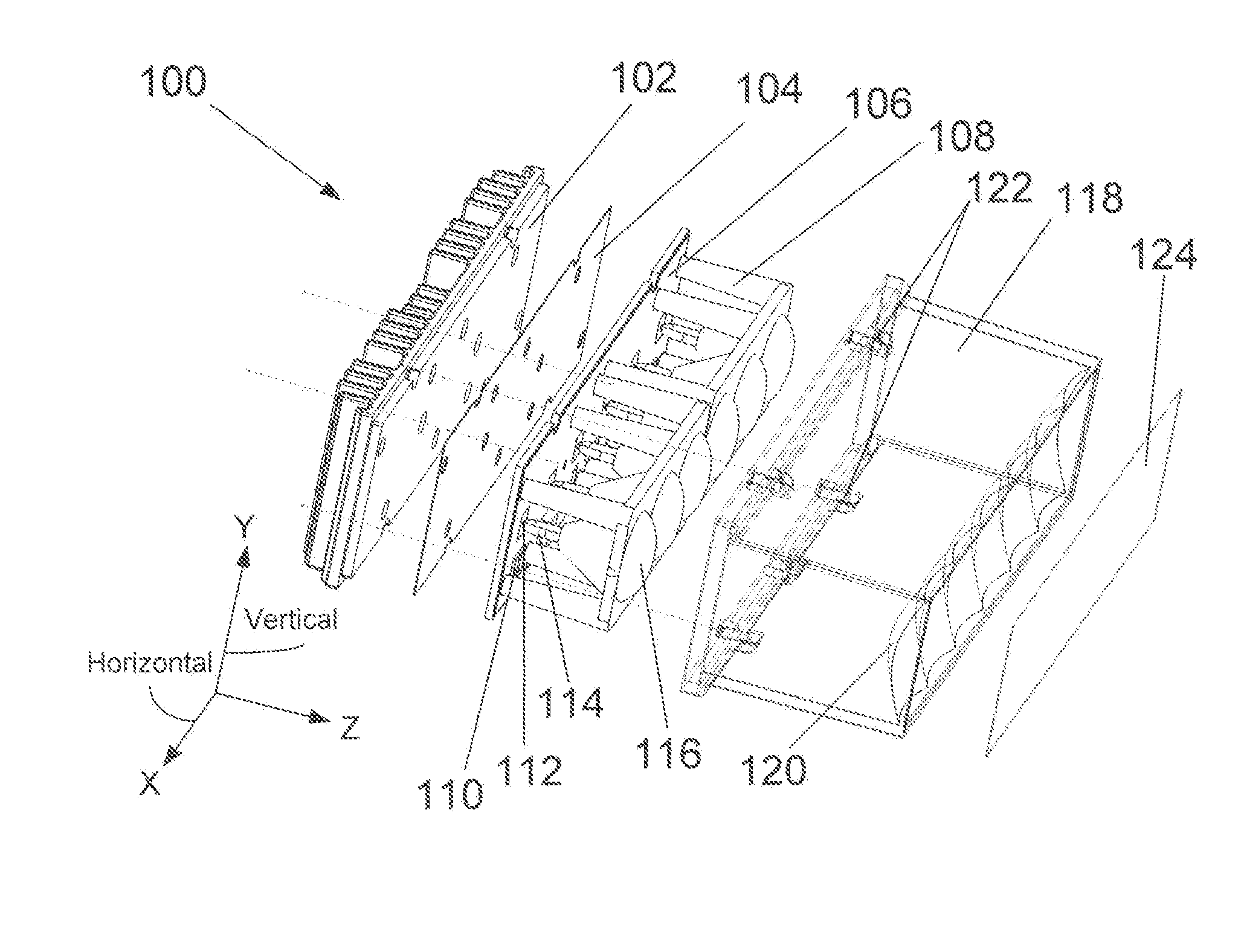
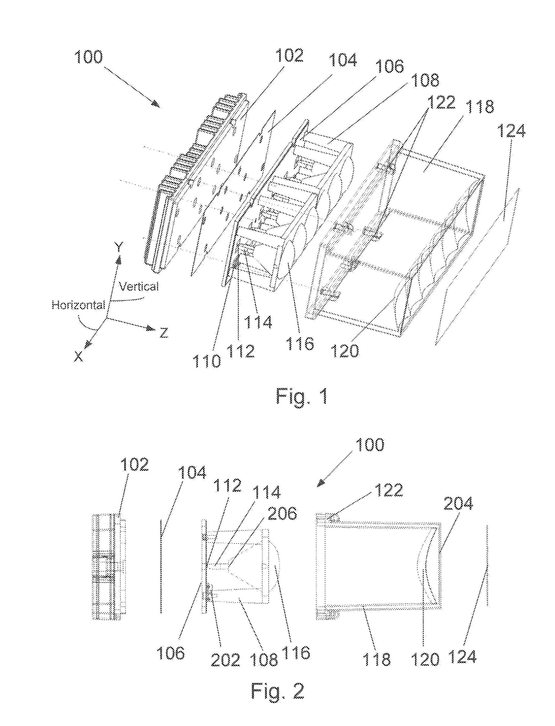
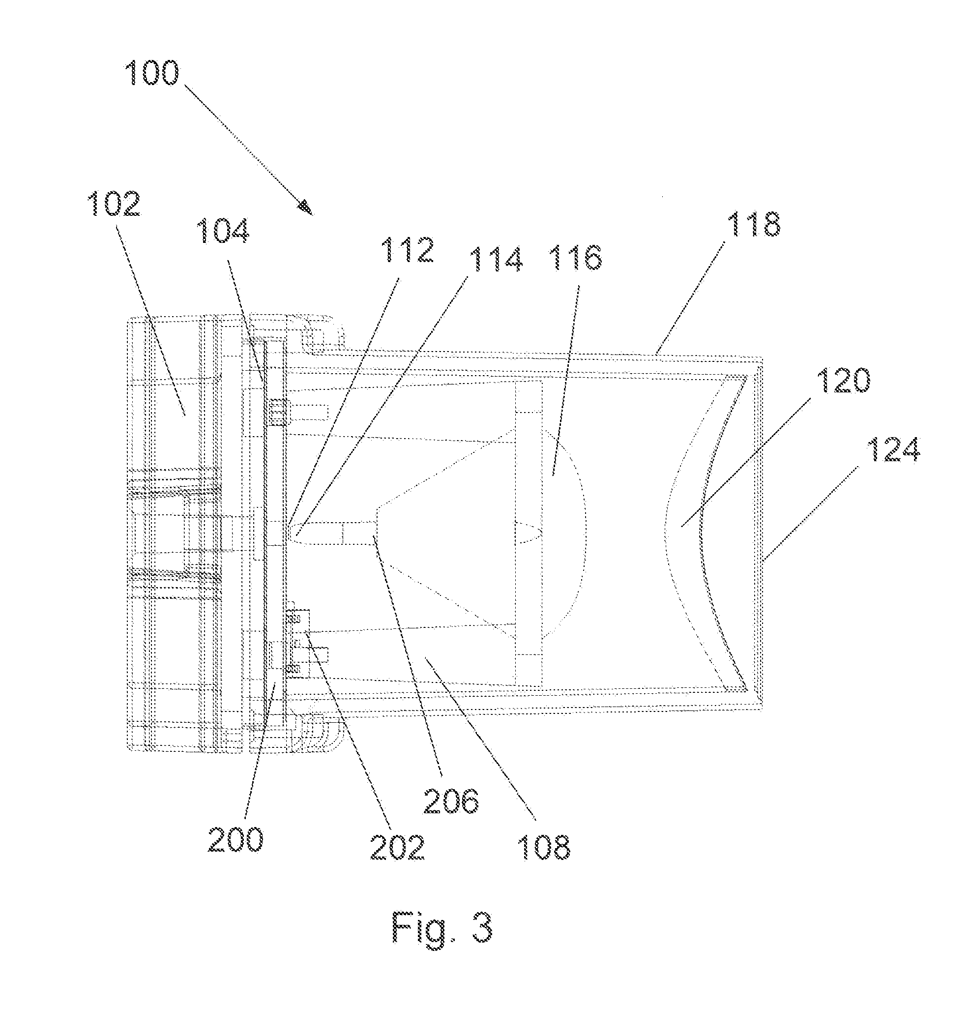
[0047]FIGS. 1, 2 and 3 show, respectively, an exploded isometric view of a preferred embodiment of the LED module designated generally at 100, an exploded view of LED module 100 in the Y-Z plane, and a collapsed side view of LED module 100 in the Y-Z plane. The LED module 100 comprises a “Chip-on-Board” (COB) metal core substrate printed circuit board (PCB) 106 with six (6) individual LED die 112 shown optically coupled to an associated individual collection optic 114, one each for each LED die 112. Each collection optic 114 has an input aperture on the order of the size of a square LED die 112, 1.1 mm, for example. The collection optic 114 is described in detail below.

[0048]The light that exits the output aperture of an individual collection optic 114...


PUM


Abstract

The present invention uses “Chip-on-Board” (COB) metal core printed circuit board (PCB) technology in conjunction with high efficiency compact imaging and non-imaging optics to provide an emergency light that is more compact, offers higher performance with respect to luminance levels (higher brightness), longer life, and lower cost relative to systems incorporating pre-packaged LED devices. The thermal impedance between the LED junction and the heat sink is significantly reduced for COB technology by placing the LED die directly on a metal core (or other high thermal conductivity material substrate), thereby increasing temperature dependant life and thermally dependant output power. Additionally, because there is no encapsulant or domed optic over the LED die initially, it is possible to get a much more compact and efficient substantially Etendue (area, solid angle, index squared product) preserving collection optic directly over the die. Cost is significantly reduced for COB configurations due to elimination of the expense of additional components attached to the LED die for the case of pre-packaged LED devices.

Description

FIELD OF THE INVENTION[0001]This invention, in general, relates to emergency lighting apparatus and, more particularly, to the use of light emitting diodes (LEDs) in high luminance emergency lighting systems.BACKGROUND OF THE INVENTION[0002]High brightness light emitting diode (LED) light sources are in high demand for challenging applications including emergency lighting. Prior art in the emergency lighting field typically utilize either tungsten or tungsten halogen lamps with colored filters or, more recently, systems incorporating pre-packaged high brightness LEDs. Emergency lights are used on vehicles such as police, fire, ambulance, tow trucks, construction vehicles, plows, as well as on vehicles in the aviation and marine fields.[0003]Generally, emergency lighting is relatively narrow in spectral width, with the most widely used colors including blue, green, amber, and red. In some cases there is a demand for white light as well. Filtered halogen or tungsten halogen lamps by t...

Claims


Application Information

Patent Timeline
Patent Type & Authority Applications(United States)
IPC IPC(8): F21V9/16F21V1/00F21V9/00H01L33/00
CPCB60Q1/2611F21V5/008F21V13/04F21V13/12G02B19/0066G02B19/0028F21Y2103/10F21V29/74F21V29/85F21V29/763F21V7/005F21V7/06F21Y2115/10F21K9/00F21V13/14
Inventor BRUKILACCHIO, THOMAS JOHN
Owner INNOVATIONS & OPTICS
Why Eureka
Try Eureka