Apparatus for Detecting the Leakage of Heavy Water in Nuclear Reactor System and Detection Method Using the Same

a technology for heavy water and nuclear reactors, which is applied in the direction of greenhouse gas reduction, instruments, optical radiation measurement, etc., can solve the problems of inability to analyze an air test sample, low measurement sensitivity, and critical affecting the stability of nuclear energy production facilities, etc., and achieves low cost, convenient portability, and small size

Active Publication Date: 2010-05-13
KOREA ATOMIC ENERGY RES INST +1
View PDF5 Cites 16 Cited by
  • Summary
  • Abstract
  • Description
  • Claims
  • Application Information

AI Technical Summary

Benefits of technology

[0018]Another aspect of the present invention provides an apparatus for detecting a leakage of heavy water in a nuclear reactor system,

Problems solved by technology

A leakage of heavy water in nuclear energy (or atomic power) facilities has a direct connection with a leakage of radioactivity, critically affecting the stability of a nuclear energy production facility.
In particular, because a heavy water nuclear reactor system is made up of 380 or more pressure tubes, and numerous pipes are installed in a complicated manner, the detection and monitoring of a heavy water leakage is crucial.
However, this method is disadvantageous in that measurement sensitivity is low, analysis of an air test sample is not possible, and it is not possible to measure heavy water leaked into the air.
However, although the liquid scintillation counting method has a high sensitivity in the heavy water leakage measurement, it disadvantageously incurs a great deal of maintenance and repair cost, generates a harmful waste scintillation liquid, and is extremely difficult to utilize as a real time monitoring apparatus.
The mass spectroscopy

Method used


Image

  • Apparatus for Detecting the Leakage of Heavy Water in Nuclear Reactor System and Detection Method Using the Same
  • Apparatus for Detecting the Leakage of Heavy Water in Nuclear Reactor System and Detection Method Using the Same
  • Apparatus for Detecting the Leakage of Heavy Water in Nuclear Reactor System and Detection Method Using the Same

Examples


Embodiment Construction

[0025]Exemplary embodiments of the present invention will now be described in detail with reference to the accompanying drawings. The invention may, however, be embodied in many different forms and should not be construed as being limited to the embodiments set forth herein. Rather, these embodiments are provided so that this disclosure will be thorough and complete, and will fully convey the scope of the invention to those skilled in the art. In the drawings, the shapes and dimensions may be exaggerated for clarity, and the same reference numerals will be used throughout to designate the same or like components.

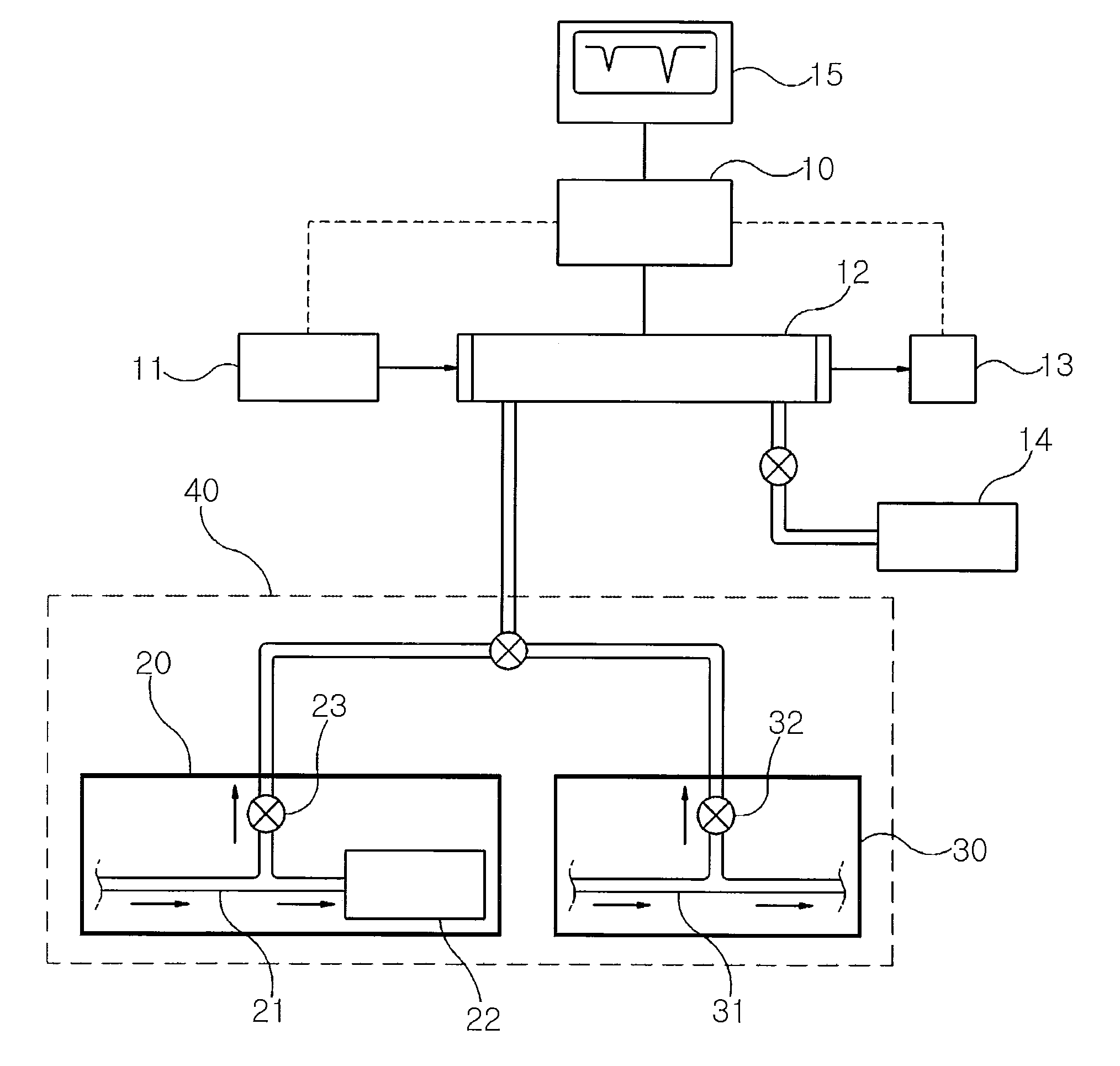
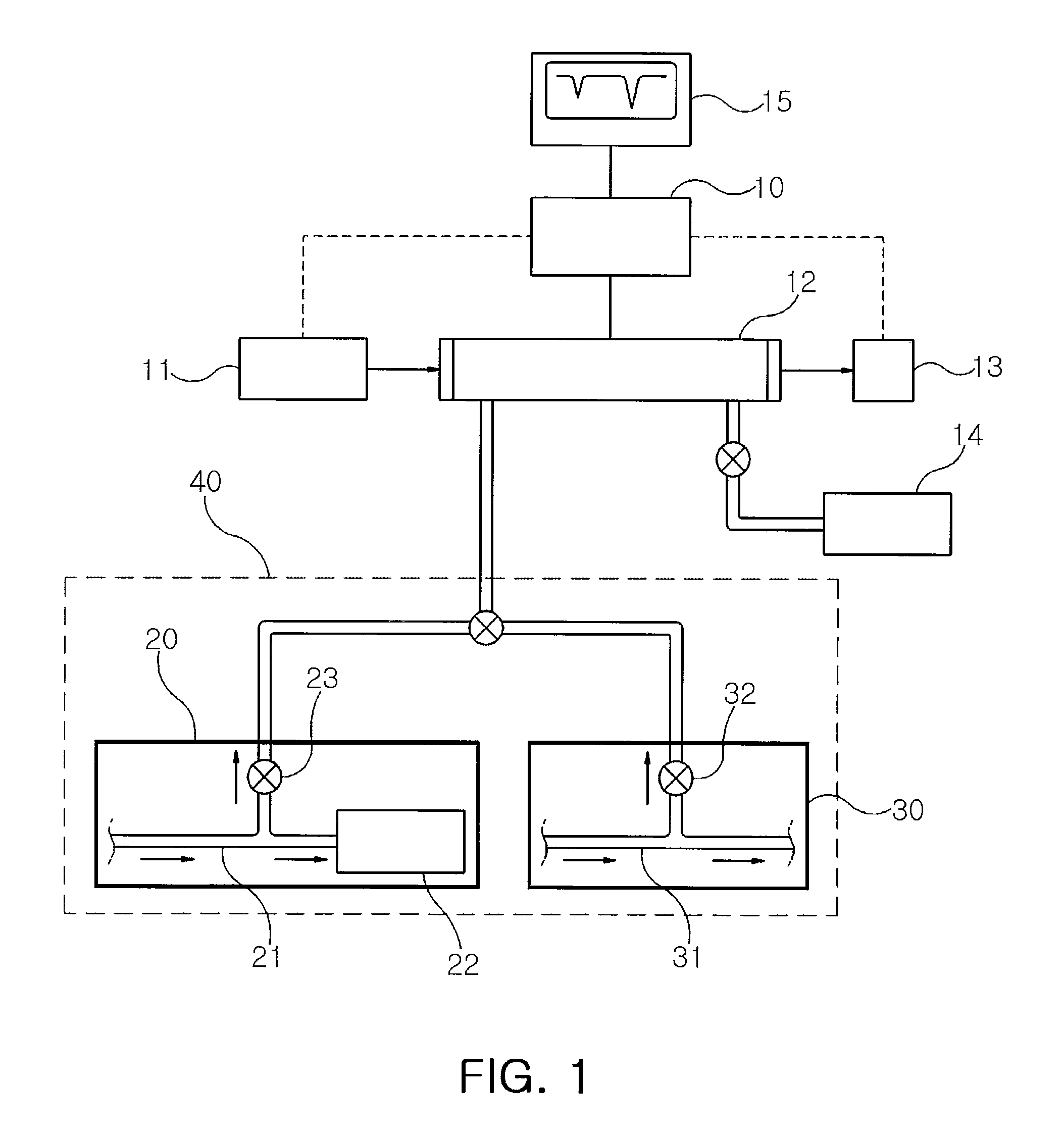
[0026]FIG. 1 is a schematic block diagram of an apparatus for detecting a leakage of heavy water in a nuclear reactor system according to an exemplary embodiment of the present invention.

[0027]With reference to FIG. 1, the apparatus for detecting a leakage of heavy water in a nuclear reactor system according to an exemplary embodiment of the present invention includes a diod...


PUM


Abstract

An apparatus and a method for detecting a leakage of heavy water in a nuclear reactor system includes: a diode laser that generates a laser beam and injects the generated laser beam to a test sample placed in a light absorption cell; the light absorption cell accommodates a gathered test sample therein; a vacuum pump adjusts a degree of vacuum in the light absorption cell; a test sample introduction unit gathers an air test sample from a location with a high possibility of a leakage of heavy water or a light water test sample from a secondary side of a steam generator and transfers the sample to the light absorption cell; an optical detector detects the laser beam which has passed through the light absorption cell; and a microprocessor controls the operation of the diode laser, the light absorption cell, the vacuum pump, the test sample introduction unit, and the optical detector, receives a detect signal from the optical detector, and analyzes an absorption spectrum signal.

Description

CROSS-REFERENCE TO RELATED APPLICATIONS[0001]This application claims the priority of Korean Patent Application No. 2008-0112620 filed on Nov. 13, 2008, in the Korean Intellectual Property Office, the disclosure of which is incorporated herein by reference.BACKGROUND OF THE INVENTION[0002]1. Field of the Invention[0003]The present invention relates to an apparatus for detecting a leakage of heavy water in a nuclear reactor system and a method for detecting a leakage of heavy water using the same, and more particularly, to an apparatus for detecting a leakage of heavy water in a nuclear reactor system capable of sensitively monitoring a leakage of heavy water within a nuclear reactor system by sampling the air or by sampling a secondary side of a steam generator in real time by taking an air test sample around a pressure tube or a delayed neutron tube of the nuclear reactor system or a test sample from the secondary side of the steam generator, and detecting and measuring the concentr...

Claims


Application Information

Patent Timeline
IPC IPC(8): G01M3/38G01N21/84G01J3/00
CPCG01J3/4338G01N1/26G01N21/031G01N21/05G01N21/3554G21C17/002G01M3/222G01M3/38G01N21/359Y02E30/30G21C17/02G21C17/022
Inventor HAN, JAE MINJEONG, DO YOUNGKO, KWANG HOONKIM, TAEK SOO
Owner KOREA ATOMIC ENERGY RES INST
Why Eureka
Try Eureka