

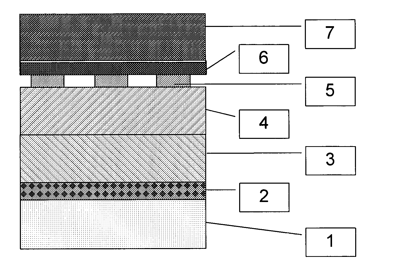
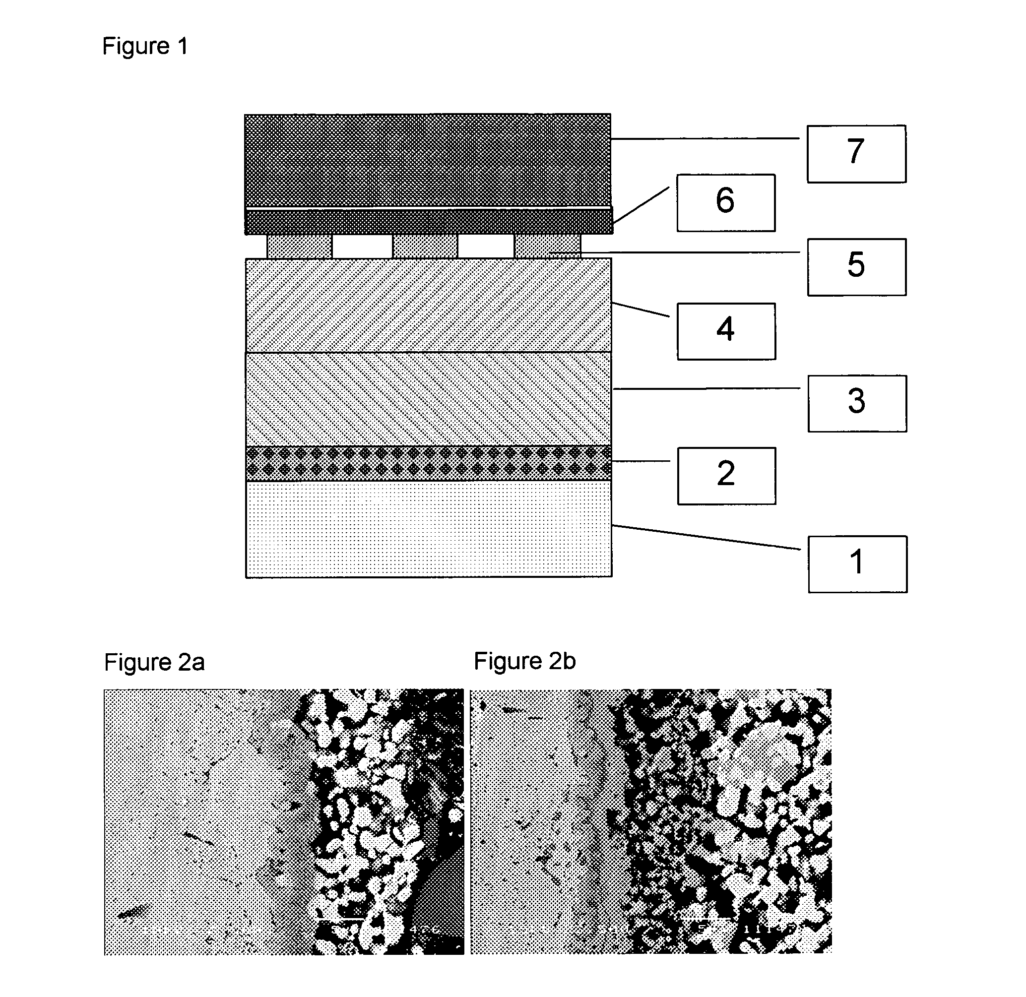
Method of producing a multilayer barrier structure for a solid oxide fuel cell
a solid oxide fuel cell and multi-layer barrier technology, which is applied in the manufacture of final products, electrochemical generators, coatings, etc., can solve the problems of affecting catalyst performance, high cost of final cells, and fuel cell mass production, and achieve the effect of minimizing electrical contact resistance and cost effectiv
- Summary
- Abstract
- Description
- Claims
- Application Information
AI Technical Summary
Benefits of technology
Problems solved by technology
Method used
Image

Examples
example 1
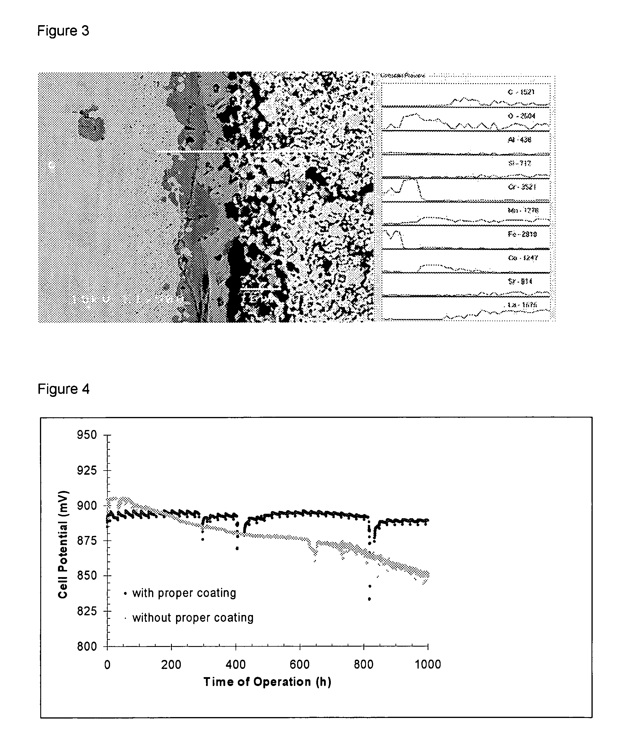
[0086]Crofer 22APU was cleaned and slurry-coated with a 7 μm thick layer of cobalt oxide (d50=2.5 μm), dried and further slurry-coated with a 20 μm thick layer of 90 wt % LSM and 10 wt % cobalt oxide. With the coated part facing the cathode of a solid oxide fuel cell (SOFC) and incorporated into a SOFC-stack, the metal part was heated in flowing air (5.4 ml / min / cm2 surface area) by 3° C. per minute to 650° C. and held at the temperature for 2 hours to burn out any residual organic binder before heating under the same conditions to 950° C., where it was held for 3 hours in order to form the spinel barrier layer on the metal surface in the cathode compartment. The SOFC-stack was then cooled to operating temperature (750° C.) and connected to an electrical load, where the degradation rate, 0.2% per 1000 hours, was assessed at a current load of 0.25 A / cm2 cell area.
example 2
[0087]Sandvik 0YC44 was cleaned and slurry-coated with a 7 μm thick layer of cobalt oxide and copper oxide (2:1 wt / wt), dried and further slurry-coated with a 20 μm thick layer of 60 wt % LSM 30 wt % LSFC and 10 wt % cobalt oxide. With the coated part facing the cathode of a solid oxide fuel cell and incorporated into a SOFC-stack the metal part was heated in flowing air (5.4 ml / min / cm2 surface area) by 3° C. per minute to 550° C. and held at the temperature for 2 hours to burn out any residual organic binder before heating in a flowing mixture of air and nitrogen (1:50 vol:vol) at 3° C. per minute to 950° C., where it was held for 4.5 hours in order to form the spinel barrier layer on the metal surface in the cathode compartment. The SOFC-stack was then cooled to operating temperature (750° C.) and connected to an electrical load, while feeding air to the cathode compartment.
example 3
[0088]ZMG232 was cleaned and slurry-coated with a 5 μm thick layer of copper oxide and manganese oxide (4:1 mol / mol), dried and further slurry-coated with a 25 μm thick layer of 50 wt % LSM 30 wt % LSC and 20 wt % cobalt oxide. With the coated part facing the cathode of a solid oxide fuel cell and incorporated into a SOFC-stack, the metal part was heated in flowing air by 3° C. per minute to 550° C. and held at the temperature for 2 hours to burn out any residual organic binder before heating in a flowing mixture of air and nitrogen (1:9 vol:vol) at 5° C. per minute to 950° C., where it was held for 4 hours in order to form the spinel barrier layer on the metal surface in the cathode compartment. The SOFC-stack was then cooled to operating temperature (850° C.) and connected to an electrical load.
PUM
| Property | Measurement | Unit |
|---|---|---|
| temperature | aaaaa | aaaaa |
| temperature | aaaaa | aaaaa |
| temperature | aaaaa | aaaaa |
Abstract
Description
Claims
Application Information