Elastomeric particle having an electrically conducting surface, a pressure sensor comprising said particles, a method for producing said sensor and a sensor system comprising said sensors

a technology of electrical conductivity and elastomeric particles, applied in the field of pressure sensors, can solve the problems of quiescent impedance, mismatched mechanical properties, and available systems for measuring pressure on body parts, and achieve the effects of reducing creep, hysteresis and/or electrical aging, and reducing creep

Active Publication Date: 2010-05-27
SWELLING SOLUTIONS
View PDF83 Cites 24 Cited by
  • Summary
  • Abstract
  • Description
  • Claims
  • Application Information

AI Technical Summary

Benefits of technology

[0023]Such particles may thus be utilized to form a composite material having pressure sensitive electrical properties and reduced creep, hysteresis and / or electrical aging, as compared with prior art composite materials.
[0024]According to a second aspect, reduced creep, hysteresis and / or electrical aging, as compared with prior art composite materials there is provided a pressure sensor element, comprising a plurality of particles having at least conducting surfaces, said particles being arranged as at least one particle layer on a non-conducting elastomeric portion.

Problems solved by technology

Presently available systems for measuring pressure on a body part, however, suffer from a number of drawbacks.
Major issues with existing measurement systems have been identified in the areas of mismatched mechanical properties (body / device impedance mismatches and resulting interface stress modification), sensitivity (often too high), quiescent impedance (often nearly infinite), nonlinearity, poor repeatability (cycle to cycle and insertion to insertion), creep, hysteresis, and sensitivity to curvature, temperature-pressure-humidity, etc.
Such spaces and surfaces are not available in the case of devices for measuring pressure on a body part.
When such composites are used in practice, strain related damage occurs easily, and as such, creep, hysteresis, and electrical aging are all increased significantly.
At such high loading levels so as to induce finite quiescent impedance, the viscoelastic properties of the composite degrade dramatically and their usefulness as “pressure sensors” is greatly diminished.
It is recognized that this type of sensor does not provide a smooth resistance-load curve.
Such sensors do not provide the desired accuracy needed in measuring pressure on a body part.

Method used


Image

  • Elastomeric particle having an electrically conducting surface, a pressure sensor comprising said particles, a method for producing said sensor and a sensor system comprising said sensors
  • Elastomeric particle having an electrically conducting surface, a pressure sensor comprising said particles, a method for producing said sensor and a sensor system comprising said sensors
  • Elastomeric particle having an electrically conducting surface, a pressure sensor comprising said particles, a method for producing said sensor and a sensor system comprising said sensors

Examples


first embodiment

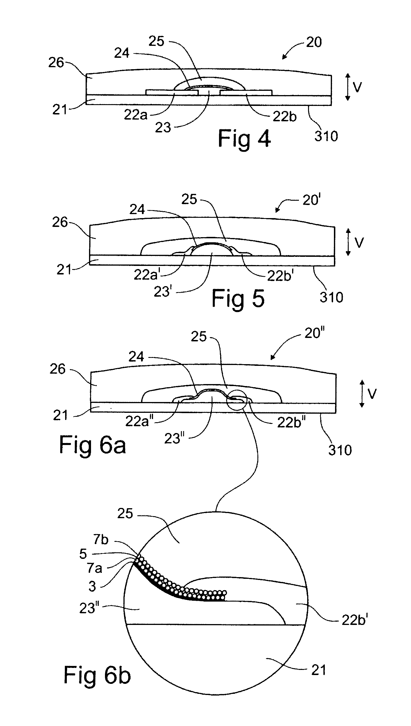
[0108]FIG. 4 schematically illustrates a pressure sensor element 20. The drawing is magnified, and the vertical direction V is greatly exaggerated. The measurement side is indicated by reference numeral 310. The sensor element 20 is based on a substrate 21, upon which a pair of electrodes 22a, 22b are arranged. The electrodes may, but do not need to, be co-planar. Electrodes 22a, 22b may be provided by patterning a conducting material onto the substrate / first elastomeric portion in any known manner. A first nonconducting elastomeric portion 23 is arranged between the electrodes. The first elastomeric portion 23 may cover opposing edge portions of the electrodes 22a, 22b and it may have a maximum thickness which is larger than that of the electrodes. The thickness of the first elastomeric portion 23 may taper or otherwise diminish towards its edges.

[0109]On the first elastomeric portion 23, one or more conducting layers 24 may be arranged. Such conducting layers may comprise elastome...

second embodiment

[0141]FIG. 8 schematically illustrates a sensor element 30′, which is similar to the one of FIG. 7, but provided with a second substrate 31a, with a third electrode 32c. The second substrate is spaced from the first substrate, and may be “floatingly” arranged in the composite material 33. The second substrate 31a with its associated electrode may be produced in the same way as the first substrate 31. The third electrode 32c can be used to facilitate preferential alignment within the composite material 33 during fabrication, augment the electrical impedance of the sensor element 30, provide more suitable area within the composite material 33 where impedance measurements can be taken, preferentially spread applied stress over the composite material 33, provide a means of measuring pressure gradients applied to the sensor element 30, or electrically shield the sensor element 30 from the surroundings.

third embodiment

[0142]FIG. 9 schematically illustrates a sensor element 30″, wherein a non-conducting elastomeric portion 35 is provided between the electrodes 32a, 32b in a manner similar to that of FIG. 4 or 5, e.g., in order to reduce stress concentrations around the edges of the electrodes, to control stresses in the composite material 33′, to separate the stress and field concentrations within the composite material 33′ and / or to facilitate preferential alignment in the composite material 33′ during fabrication of the sensor element 30″. The elastomeric portion 35 may be further foamed to alter the hardness and the Poisson's ratio of this portion of the sensor element 30″. This provides a further means of controlling pressure sensitivity of the sensor element 30″

[0143]Furthermore, in FIG. 9, the portion of the composite material 33′ extending between the electrodes 32a, 32b may be structured, e.g., made narrower, so as to further control sensitivity of the electrical impedance of the composite...


PUM

PropertyMeasurementUnit
thicknessaaaaaaaaaa
thicknessaaaaaaaaaa
thicknessaaaaaaaaaa

Abstract

An elastomeric particle (1, 1, 1″) comprises a non-conducting elastomeric body (2) having an electrically conducting surface (4a, 4b, 6). Pressure sensor elements (20, 20′, 20″; 30, 30′, 30″, 30′″) comprising such elastomeric particles are disclosed, as well as sensor clusters (50″, 50′″, 50IV, 50V, 50VI, 50VII, 70) comprising such sensor elements. There is also disclosed a pressure sensor element (40, 40′, 40″, 40′″, 40IV, 40V, 40VI, 40VII), comprising a resistive element (44, 44′, 44″) providing a conduction path, a first electrode (42a, 42a-1, 42a-2, 42a-3, 42a-4, 42a-5, 42a-6), connected to the resistive element, a second electrode (42b, 42b′), which in a quiescent state is spaced from said first electrode, wherein the second electrode, when the pressure sensor element is subjected to a pressure, is arranged to contact said first electrode or said resistive element. Systems comprising such sensor elements and sensor clusters are disclosed, as well as methods of their fabrication.

Description

BACKGROUND OF THE INVENTION[0001]The present disclosure relates to pressure sensors and systems comprising such sensors. In particular, the present disclosure is directed towards sensors and sensor systems that may be used for measuring pressure on a body part.[0002]Hence, the present disclosure relates to particles that may form part of sensor elements, sensor systems, clusters of sensor elements and devices for measuring pressure on a body part.[0003]There are many applications in which it may be desirable to measure pressure on a body part. As a non-limiting example, it may be desirable to measure pressure on a body part in connection with compression treatment of the body part. Compression therapies may be used for treatment and / or prophylaxis of a number of conditions, including, but not limited to, Deep Vein Thrombosis (DVT), vascular disorders, circulatory disorders, edemas, heart conditions (treated by counterpulsation), lymphedema, burns, injuries, and embolisms.[0004]Some ...

Claims


Application Information

Patent Timeline
Patent Type & Authority Applications(United States)
IPC IPC(8): A61B5/103G01L9/02A61H1/00
CPCH01B1/22G01L1/205H01C10/12H01C10/106A61B5/4848G01L9/02A61H9/0078A61B2562/0247
Inventor TOTH, LANDYWALLEN, JOHAN
Owner SWELLING SOLUTIONS
Why Eureka
Try Eureka