Adhesive tape, particularly for bonding optoelectronic components

Inactive Publication Date: 2010-06-17
TESA SE
View PDF16 Cites 20 Cited by
  • Summary
  • Abstract
  • Description
  • Claims
  • Application Information

AI Technical Summary

Benefits of technology

[0014]An adhesive tape is proposed which is easy to apply and ensures a degree of protection of the laminate edge from water/water vapour penetration that is like that ensured by the laborious silicone sealing.
[0015]It has emerged that a foam adhesive tape, despite the danger of damage to the foam in the course of enframing, is suitable for sealing provided this adhesive tape additionally comprises a suitable barrier film. Given an appropriate arrangement, the barrier film is sufficiently protected, and so in general, even in the event of damage to the mechanically sensitive foam, the film is unaffected and hence the barrier effect of the adhesive tape is maintained. Contrary to all expectation, moreover, the adhesive tape can be placed readily around the laminate corners and edges, without the adhesive tape lifting, in spite of the significantly increased resilience. This applies in particular to the preferred form of application where the side with the barrier film faces the laminate edge, and the side with the foam faces the frame.
[0016]Furthermore, the barrier film affords the advantage that as a result of this film the adhesive tape overall has a more dimensionally stable design, particularly with respect to extension. This is the case in particular when the barrier film is composed, preferably, of a layer of an oriented film, as for example of a metallized polyester film or of a polyolefin film

Problems solved by technology

A technical challenge for the realization of a sufficient working life and function of (opto)electronic systems in the field of organic and/or inorganic (opto)electronics, especially in the field of organic (opto)electronics, is seen as being the protection of the components present therein against permeants.
Thus, for example, oxidation of the constituents may drastically reduce the luminosity power, in the case, for instance of light-emitting systems such as electroluminescent lamps (EL lamps) or organic light-emitting diodes (OLEDs), the contrast in the case of electrophoretic displays (EP displays), or the efficiency in the case of solar cells, within a very short time.
This results in addition of the voltage of the individual cells.
When the module is being pressed in, therefore, the adhesive tape may be damaged, possibly producing cracks in the foam, through which, in turn, rainwater may penetrate to the lam

Method used


Image

  • Adhesive tape, particularly for bonding optoelectronic components
  • Adhesive tape, particularly for bonding optoelectronic components
  • Adhesive tape, particularly for bonding optoelectronic components

Examples


example 1

Comparative

[0070]An adhesive tape with a PE foam 1000 μm thick (Alveo), with a density of 67 kg / m3, is corona-treated and then provided on both sides with 50 g / m2 of a resin-modified adhesive (tesa 4957) and subjected to measurement.[0071]Permeation of water: 12 g / m2 d[0072]Conductivity measurement: short circuit (resistance

[0073]The adhesive tape does not have a sufficient barrier effect; water is able to diffuse into the joint and short-circuit the conductor (aluminium foil) with the frame.

example 2

Comparative

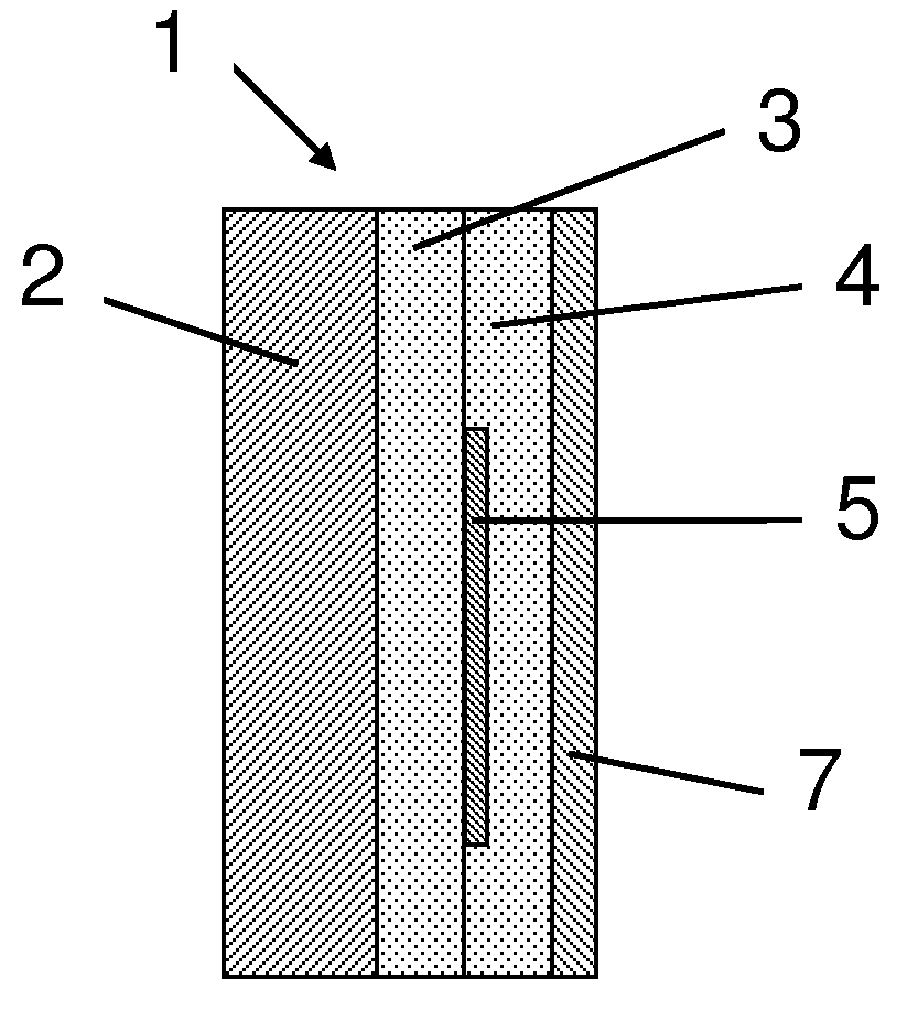
[0074]An adhesive tape with a PE foam 1000 μm thick, with a density of 67 kg / m3, is corona-treated and then provided on both sides with 50 g / m2 of a resin-modified adhesive (tesa 4957). Furthermore, on the side facing the laminate edge, the adhesive tape is provided with a 23 μm polyester film and with an additional layer of adhesive which is identical to those specified above. The resulting product structure is as follows:[0075]a) adhesive[0076]b) foam[0077]c) adhesive[0078]d) polyester film[0079]e) adhesive

[0080]The adhesive e) is facing the laminate edge.[0081]Permeation of water: 10 g / m2 d[0082]Conductivity measurement: short circuit (resistance

[0083]The adhesive tape does not have a sufficient barrier effect; water is able to diffuse into the joint and short-circuit the conductor (aluminium foil) with the frame.

example 3

Inventive

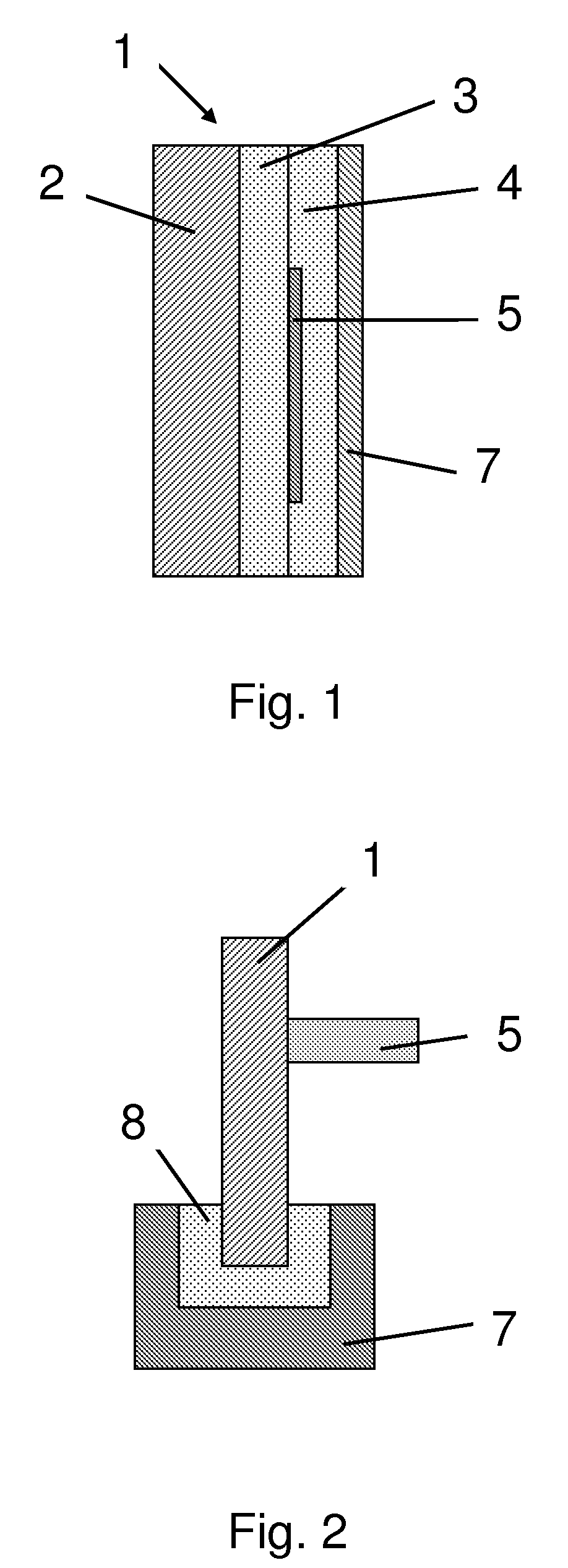
[0084]An adhesive tape with a 1000 μm thick PE foam having a density of 67 kg / m3 is corona-treated and then provided on both sides with 50 g / m2 of a resin-modified adhesive (tesa 4957). Additionally, on the side facing the laminate edge, a 23 μm polyester film which has been vapour-coated with a layer of aluminium 20 nm thick (Donmore Europe in 79111 Freiburg), and an additional layer of adhesive which is identical with those specified above, are applied. The resulting product structure is as follows:[0085]a) adhesive[0086]b) foam[0087]c) adhesive[0088]d) metallized polyester film[0089]e) adhesive

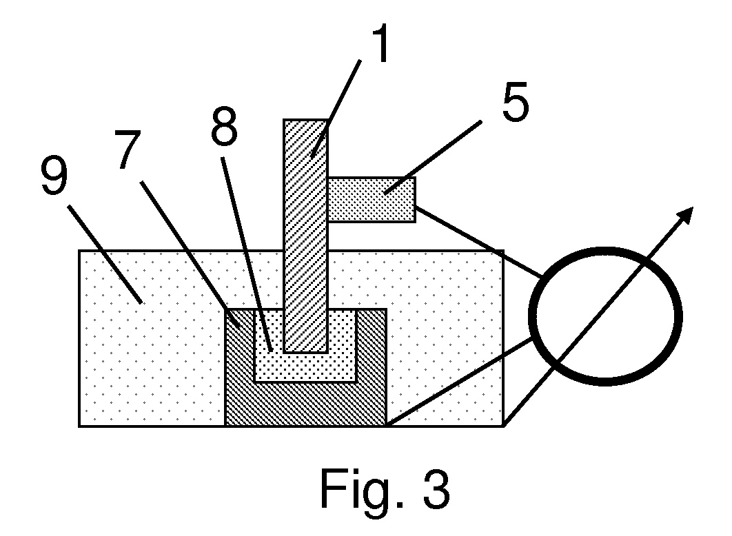
[0090]The adhesive e) faces the laminate edge.[0091]Permeation of water: 1 g / m2 d[0092]Conductivity measurement: 25 Mohm

[0093]The adhesive tape has a sufficient barrier effect; no water / water vapour is able to diffuse into the joint of the laminate and short-circuit the conductor (aluminium foil) with the frame.


PUM

PropertyMeasurementUnit
Temperatureaaaaaaaaaa
Fractionaaaaaaaaaa
Thicknessaaaaaaaaaa

Abstract

An adhesive tape for bonding optoelectronic components comprises a foam layer and two adhesive layers on the outside. The foam layer is located between top and bottom adhesive layers. A barrier film is, optionally, present between the adhesive layers.

Description

FIELD OF THE INVENTION[0001]The invention relates to an adhesive tape intended more particularly for the adhesive bonding of optoelectronic components, with particular preference photovoltaic laminates.BACKGROUND OF THE INVENTION[0002]Electronic and optoelectronic systems are being used more and more often in commercial products or are about to be introduced to the market. The term optoelectronics (sometimes also called optronics or optotronics) came about from a combination of optics and microelectronics, and in its widest sense encompasses all products and processes which allow the conversion of electronically generated data and / or energy into light emission and vice versa. Such systems include organic or inorganic electronic structures, examples being organic, organometallic or polymeric semiconductors or else combinations of these. Depending on the desired application, these systems and products are of rigid or flexible design. A technical challenge for the realization of a suff...

Claims


Application Information

Patent Timeline
IPC IPC(8): B32B15/085H01L31/042C09J7/29
CPCC09J7/0289C09J7/0296Y10T428/28C09J2400/243Y10T428/2804C09J2201/162C09J7/26C09J7/29C09J2301/162C09J2203/326
Inventor BURMEISTER, AXELBUNDE, BERND
Owner TESA SE
Why Eureka
Try Eureka