Fluorescent substance, method for producing the same, and light-emitting device using the same

a technology of fluorescent substance and light-emitting device, which is applied in the field of fluorescent substance, can solve the problems of insufficient emission of fluorescent substance described in patent document 2, inability to yield white light when combined with a blue, and inability to yield white light, so as to avoid the influence of surface defects, high emission intensity, and high emission intensity

Active Publication Date: 2010-07-01
NAT INST FOR MATERIALS SCI
View PDF8 Cites 56 Cited by
  • Summary
  • Abstract
  • Description
  • Claims
  • Application Information

AI Technical Summary

Benefits of technology

[0029]According to the fluorescent substance of the present invention, sufficiently high emission intensity can be obtained by a fluorescent substance comprising a crystal having the same crystal structure with an α-type silicon nitride crystal, or an α-sialon crystal, which includes at least an M(0) element (where M(0) represents one or two elements selected from Sr and La), an M(1) element (where M(1) represents one or more elements selected from Mn, Ce, Pr, Nd, Sm, Eu, Tb, Dy, Ho, Er, Tm, and Yb), Si, Al, and nitrogen; a fluorescent substance further including oxygen; or a fluorescent substance further including an M(2) element (where M(2) represents one or more elements selected from Li, Na, Be, Mg, Ca, Ba, Sc, Y, Gd, and Lu).
[0030]Moreover, the fluorescent substance of the present invention is also an α-sialon-based fluorescent substance comprising an α-sialon phase and the remainder which includes one or more materials selected from β-sialon, unreacted silicon nitride, oxynitride glass, and SrSi6N8. When one or more materials selected from β-sialon, unreacted silicon nitride, oxynitride glass, and SrSi6N8 are included in addition to the α-sialon phase, sufficiently high emission intensity can be obtained if the content of the α-sialon phase is 90 mass % or more.
[0031]In addition, when the fluorescent substance of the present invention is a powder having an average particle diameter of 0.1 μm to 50 μm, influences of surface defects can be avoided, the excitation light can be sufficiently absorbed, and the light emission having high intensity can be obtained.
[0032]According to the fluorescent substance of the present invention, when the average aspect ratio of primary particles constituting the α-sialon powder is 3 or less, not only the dispersibility in a resin is improved, but also the excitation light can be effectively absorbed and sufficiently high emission intensity can be obtained.
[0033]Furthermore, when a trace amount of impurity such as fluorine and boron is included in the fluorescent substance of the present invention, the emission intensity is further improved.
[0034]In addition, in a method for producing a fluorescent substance comprising a crystal having the same crystal structure with an α-type silicon nitride crystal, or an α-sialon crystal, which includes at least Sr, an M(1) element (where M(1) represents one or more elements selected from Mn, Ce, Pr, Nd, Sm, Eu, Tb, Dy, Ho, Er, Tm, and Yb), Si, Al, and nitrogen; a fluorescent substance further including oxygen; or a fluorescent substance further including an M(2) element (where M(2) represents one or more elements selected from Li, Na, Be, Mg, Ca, Ba, Sc, Y, La, Gd, and Lu), one or more materials selected from MSiN2, M2Si5N8, M3Al2N4, and MSi6N8 can be used as an M-containing compound (where M represents one or more elements selected from divalent elements in the element group consisting of Sr and M(1)), and LiSi2N3 can be used as an Li-containing compound. By using these compounds, the reactivity in the calcination process can be improved, and the fluorescent substance having higher brightness can be obtained.

Problems solved by technology

However, the fluorescent substance described in Patent Document 2 is not sufficient in the emission intensity since the proportion of Sr and / or Mg relative to Ca is within a range of 40 mole % at most.
In addition, the fluorescent substance comprising Sr alone described in this document serves as a blue-green light-emitting fluorescent substance having an emission peak wavelength of 512 nm, and thus is not able to yield white light when combined with a blue LED.
In addition, the fluorescent substance described in Patent Document 3 has a peak emission wavelength within the range of 600 to 650 nm, and thus is not able to yield white light having a high color temperature when combined with a blue LED to serve as a white LED.
Moreover, regarding the light-emitting devices such as illumination, a white light-emitting diode comprising a blue light-emitting diode element and an yttrium / aluminum / garnet based fluorescent substance had a characteristic of emitting bluish-white light due to a lack of a red component, and thus raised a problem of uneven color-rendering property.

Method used


Image

  • Fluorescent substance, method for producing the same, and light-emitting device using the same
  • Fluorescent substance, method for producing the same, and light-emitting device using the same
  • Fluorescent substance, method for producing the same, and light-emitting device using the same

Examples


first embodiment

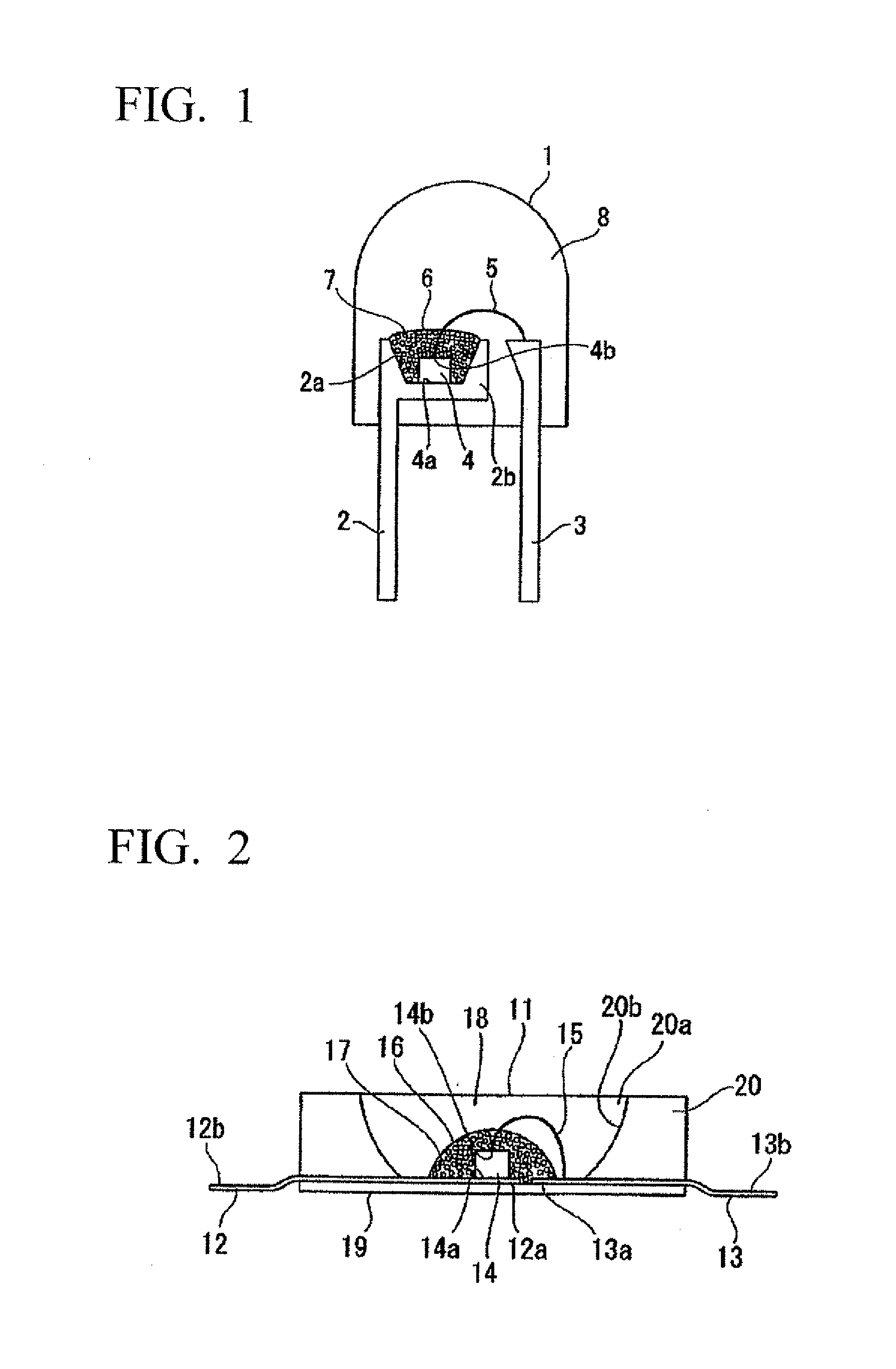
[0127]As a first embodiment of the illuminator of the present invention, a shell-type white light-emitting diode lamp (LED illuminator) 1 as shown in FIG. 1 is described.

[0128]The shell-type white light-emitting diode lamp 1 comprises a first lead wire 2 and a second lead wire 3. The first lead wire 2 has a recess 2a. On the recess 2a is mounted a blue light-emitting diode element 4. In the blue light-emitting diode element 4, a lower electrode 4a is electrically connected to the bottom face of the recess 2a by a conductive paste while an upper electrode 4b is electrically connected to the second lead wire 3 by a bonding wire (thin metal wire) 5.

[0129]The first resin 6 is a transparent resin having a fluorescent substance 7 dispersed therein, and covers all over the blue light-emitting diode element 4. The apical end 2b of the first lead wire 2 including the recess 2a, the blue light-emitting diode element 4, and the first resin 6 having the fluorescent substance 7 dispersed therein...

second embodiment

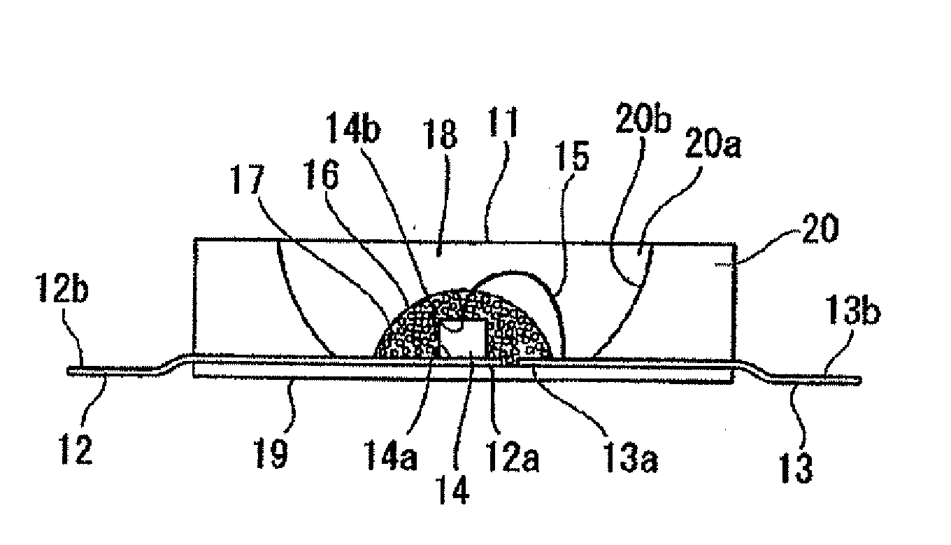
[0133]As a second embodiment of the illuminator of the present invention, a surface-mount chip-type white light-emitting diode lamp (LED illuminator) 11 as shown in FIG. 2 is described.

[0134]In the surface-mount chip-type white light-emitting diode lamp 11, a third lead wire 12 and a fourth lead wire 13 are fixed to a ceramic substrate 19 which uses a white alumina ceramics having high reflectance against visible light, ends 12a and 13a thereof are located in an approximate center of the substrate, and the other ends 12b and 13b are located outside to serve as electrodes to be soldered when being mounted on an electric substrate.

[0135]A blue light-emitting diode element diode element 14 is mounted on and fixed to the end 12a of the third lead wire 12 in a center of the substrate. The lower electrode 14a of the blue light-emitting diode element 14 and the third lead wire 12 are electrically connected by a conductive paste while the upper electrode 14b and the fourth lead wire 13 are ...

examples

[0155]The present invention is described in further detail below using examples, although the examples are disclosed for better understanding of the present invention and the present invention is in no way limited by the examples.


PUM

PropertyMeasurementUnit
refractive indexaaaaaaaaaa
temperatureaaaaaaaaaa
emission peak wavelengthaaaaaaaaaa

Abstract

The present invention provides a fluorescent substance exhibiting higher brightness as compared to conventional fluorescent substances, a method for producing the same, and a light-emitting device using such a fluorescent substance. Specifically, the fluorescent substance comprises an α-sialon crystal structure having the same crystal structure with an α-type silicon nitride crystal, which includes at least an M(0) element (where M(0) represents one or two elements selected from Sr and La), an M(1) element (where M(1) represents one or more elements selected from Mn, Ce, Pr, Nd, Sm, Eu, Tb, Dy, Ho, Er, Tm and Yb), Si, Al, and nitrogen.

Description

TECHNICAL FIELD[0001]The present invention relates to a fluorescent substance which mainly consists of an inorganic compound, and the application thereof. More specifically, the application is associated with light-emitting devices such as illumination devices and display devices which use a characteristic of the fluorescent substance, that is, a property of emitting fluorescence having a long wavelength of 550 nm or longer.[0002]Priority is claimed on Japanese Patent Application No. 2007-135477, filed May 22, 2007, and Japanese Patent Application No. 2008-079586, filed Mar. 26, 2008, the contents of which are incorporated herein by reference.BACKGROUND ART[0003]Fluorescent substances are applied to a vacuum fluorescent display (VFD), a field emission display (FED), a plasma display panel (PDP), a cathode ray tube (CRT), a white light-emitting diode (LED), and the like. In any application of these, in order to emit light from a fluorescent substance, energy for exciting the fluoresc...

Claims


Application Information

Patent Timeline
Patent Type & Authority Applications(United States)
IPC IPC(8): H01J5/08C09K11/79B32B5/00B05D5/06H01L33/50
CPCC04B35/597C04B35/6262H01L2924/181Y10T428/265H01L2224/8592H01L2224/48247H01L2224/48091C04B35/62675C04B35/6268C04B35/62685C04B2235/3201C04B2235/3203C04B2235/3205C04B2235/3206C04B2235/3208C04B2235/3213C04B2235/3215C04B2235/3224C04B2235/3225C04B2235/3227C04B2235/3229C04B2235/3262C04B2235/3852C04B2235/3865C04B2235/3873C04B2235/3878C04B2235/3891C04B2235/3895C04B2235/5296C04B2235/5436C04B2235/5445C09K11/0883C09K11/7728H01L33/502H05B33/14H01L2224/45144H01L2924/00014H01L2924/00H01L2924/00012H01L33/00
Inventor SHIOI, KOUSUKEHIROSAKI, NAOTO
Owner NAT INST FOR MATERIALS SCI
Why Eureka
Try Eureka