Systems and methods to affect anatomical structures

a technology of anatomical structure and system, applied in the field of systems and methods to affect anatomical structure, can solve the problems of limited mobility, significant impact on the quality of life of affected individuals, and certain fractures and bone defects, and require additional bone augmentation

Active Publication Date: 2010-07-01
GEORGIA TECH RES CORP +1
View PDF39 Cites 36 Cited by
  • Summary
  • Abstract
  • Description
  • Claims
  • Application Information

AI Technical Summary

Problems solved by technology

Such musculoskeletal defects often result in pain and limited mobility, and therefore significantly impact the quality of life of affected individuals.
Certain fractures and bone defects, however, require additional bone augmentation.
Though autologous bone grafting has been successful in many cases, it has significant disadvantages including limited graft material and morbidity of the donor site.
These limitations have led to increased use of allograft bone as a substitute for autologous bone.
Allograft bone, however, is inferior to autologous bone due to its reduced biological activity after processing.
In addition, allograft bone grafting is associated with a high rate of complications and late fractures as well as a risk of disease transmission.
The high failure rate of allografts is largely attributable to the inability of the graft to revascularize and remodel.
But, ceramics tend to be brittle, and polymers suffer from limited bioactivity and strength and may need to be supplemented with osteogenic cells and growth factors.
Though the focus has been to create three-dimensional scaffolds having adequate strength to support in vivo loading, most scaffolds do not provide an optimal environment for cellular function, and suffer from slow resorption kinetics.
Moreover, exogenous cells delivered at the center of these scaffolds in vivo may not survive due to the initial lack of vascularity at the defect.
Though this technique (called guided bone / tissue regeneration) has been highly successful in the dental field for bone regeneration, it has not been quantitatively evaluated for the load bearing case of long bone defects.

Method used


Image

  • Systems and methods to affect anatomical structures
  • Systems and methods to affect anatomical structures
  • Systems and methods to affect anatomical structures

Examples


example 1

Colonization and Osteogenic Differentiation of Different Stem Cell Sources on Electrospun Nanofiber Meshes

[0094]The purpose of this Example was to investigate the attachment, colonization and osteogenic differentiation of human MSCs (hMSCs) and human AFS (hAFS) cells on electrospun nanofiber meshes. This Example demonstrates that electrospun meshes are able to robustly support these functions for both cell types. Compared to tissue culture plastic, there is delayed initial attachment and proliferation, but enhanced mineralization at a later time point. Differences in the kinetics of osteogenic differentiation were observed between hMSCs and hAFS cells. Cell-seeded nanofiber meshes were also effective in colonizing three dimensional scaffolds in an in vitro model. These results provide support for the use of the nanofiber mesh as a cell delivery vehicle for the repair of bone defects in vivo.

[0095]Materials and Methods

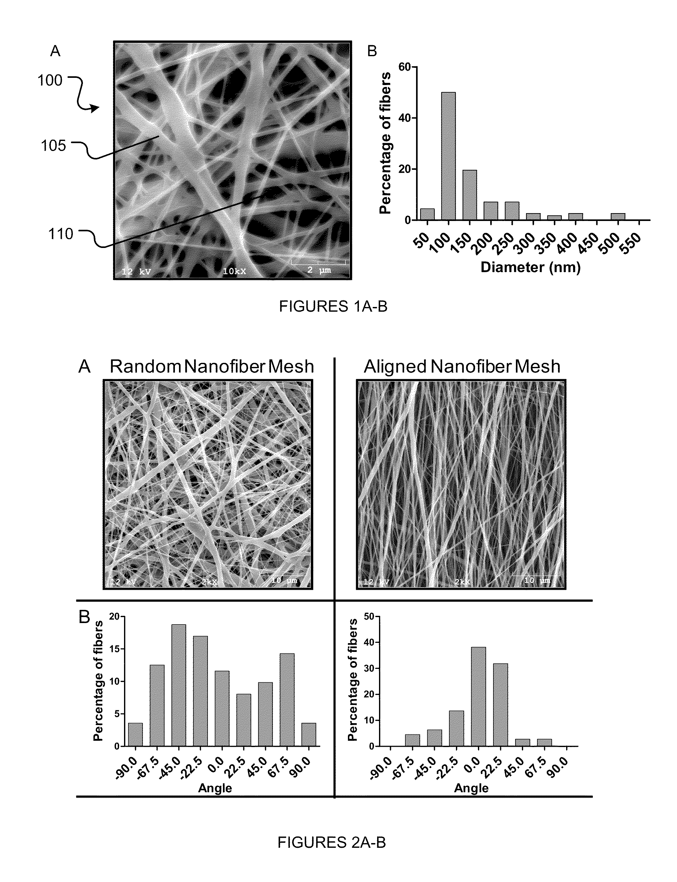
[0096]Fabrication of nanofiber meshes. A polymer solution was made...

example 2

Nanofiber Orientation and Surface Functionalization Modulate Human MSC Infiltration and Osteogenic Differentiation

[0120]Electrospun nanofiber meshes are a unique type of scaffold with structural features that, at least by scale, resemble the extracellular matrix (ECM). In addition, they exhibit large surface area and high porosity, making them suitable as a scaffold for guiding tissue regeneration by host cells. For example, in the case of a large diaphyseal bone defect, the nanofiber mesh may be able to provide cues for progenitor cells from the periosteum and marrow space to migrate into the defect region and deposit mineralized matrix. Example 1 demonstrated that nanofiber meshes made from a synthetic polymer are able to support the attachment, colonization and osteogenic differentiation of progenitor cells. Synthetic polymers, however, lack biological ligands, and are not capable of directing intracellular signaling and response. Nanofiber meshes have also been fabricated from n...

example 3

A Novel Hybrid System for Growth Factor Delivery Promotes Functional Repair of Large Bone Defects

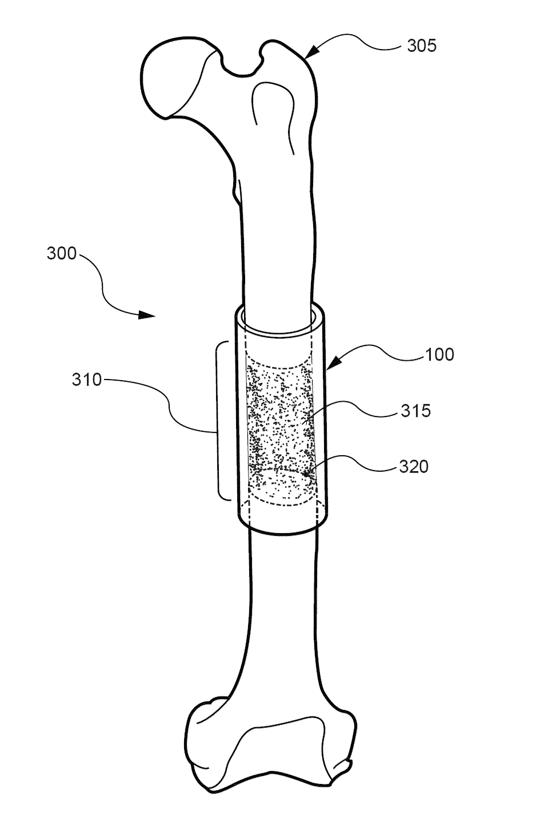
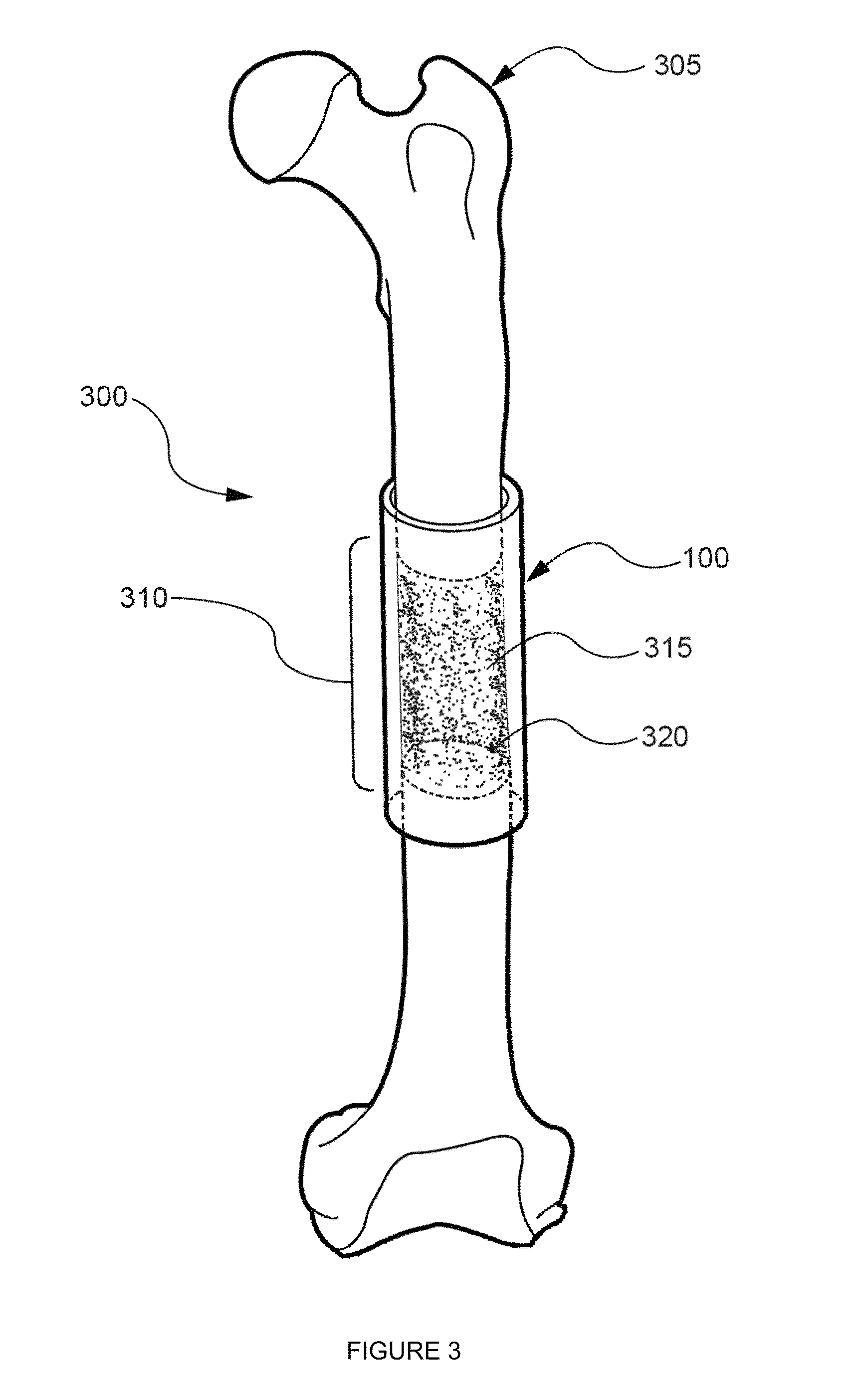
[0149]The primary objective of this Example was to develop and test a hybrid growth factor delivery system for bone repair that utilizes an electrospun nanofiber mesh and injectable alginate hydrogel. To test this system, we evaluated its ability to deliver rhBMP-2 for the repair of critically-sized segmental bone defects in vivo. For control group comparisons, we also examined the ability of the nanofiber mesh alone, and in combination with alginate hydrogel, to heal the bone defects without rhBMP-2. Finally, the effect of a perforated nanofiber mesh design on bone repair was investigated.

[0150]Materials and Methods

[0151]Fabrication of nanofiber mesh tubes. Poly (ε-caprolactone) (PCL) pellets (Sigma-Aldrich, St. Louis, Mo.) were dissolved in a 90:10 volume ratio of hexafluoro-2-propanol (HFP):dimethylformamide (DMF) (Sigma-Aldrich) to obtain a 12% (w / v) polymer solution. DMF was first s...


PUM

PropertyMeasurementUnit
pore sizeaaaaaaaaaa
diametersaaaaaaaaaa
thicknessaaaaaaaaaa

Abstract

The various embodiments of the present invention are generally directed to systems and methods to affect anatomical structures. More particularly, the various embodiments of the present invention are directed to systems and methods to regenerate bone. An aspect of the present invention comprises a system for affecting an anatomical structure, comprising: a nanofiber mesh configured to substantially conform to an anatomical structure, wherein at least a portion of the nanofiber mesh defines a fillable space; a carrier substance comprising an active agent, such as a bone morphogenetic protein, wherein the carrier substance is disposed within the fillable space.

Description

RELATED APPLICATION[0001]This application claims, under 35 U.S.C. §119(e), the benefit of U.S. Provisional Application Ser. No. 61 / 117,399, filed 24 Nov. 2008, the entire contents and substance of which are hereby incorporated by reference as if fully set forth below.STATEMENT REGARDING FEDERALLY SPONSORED RESEARCH[0002]This invention was made with U.S. Government support under Grant No. EEC-9731643 awarded by the National Science Foundation, Grant No. 1 R01 AR051336-01 awarded by the National Institutes of Health, Grant No. W81XWH-08-1-0704 awarded to the Center for Advanced Bioengineering for Soldier Survivability through the Department of Defense. The U.S. Government has certain rights in the invention.TECHNICAL FIELD OF THE INVENTION[0003]The various embodiments of the present disclosure relate generally to systems and methods to affect anatomical structures. More particularly, the various embodiments of the present disclosure are related to systems and methods to regenerate bon...

Claims


Application Information

Patent Timeline
Patent Type & Authority Applications(United States)
IPC IPC(8): A61B17/00A61F2/28
CPCA61F2002/30075A61F2002/30235A61F2002/3084A61F2002/30914A61F2002/3092A61F2210/0061A61F2230/0069A61F2240/001A61F2310/00365A61L27/3804A61L27/3834A61L27/52A61L27/54A61L27/56A61L31/146A61L31/16A61L2300/414A61L2400/12A61F2/2846A61F2/3094A61F2002/2817A61F2002/2825A61F2002/285A61L2400/06A61L2430/02A61F2002/30838A61F2/30767A61F2002/0068A61F2002/30028
Inventor GULDBERG, ROBERT E.KOLAMBKAR, YASH M.HUTMACHER, DIETMAR W.
Owner GEORGIA TECH RES CORP
Why Eureka
Try Eureka