Method For Bonding Of Concentrating Photovoltaic Receiver Module To Heat Sink Using Foil And Solder
a technology of concentrating photovoltaic and receiver modules, which is applied in the direction of paper/cardboard containers, containers, other domestic objects, etc., can solve the problems of increasing production time, difficult to keep solar cells running at temperatures below those that are required to avoid, and failure to meet the thermal requirements of a cpv system, etc., to achieve easy assembly process, long-term reliability, and high thermal conductivity interface
- Summary
- Abstract
- Description
- Claims
- Application Information
AI Technical Summary
Benefits of technology
Problems solved by technology
Method used
Image

Examples
example 1
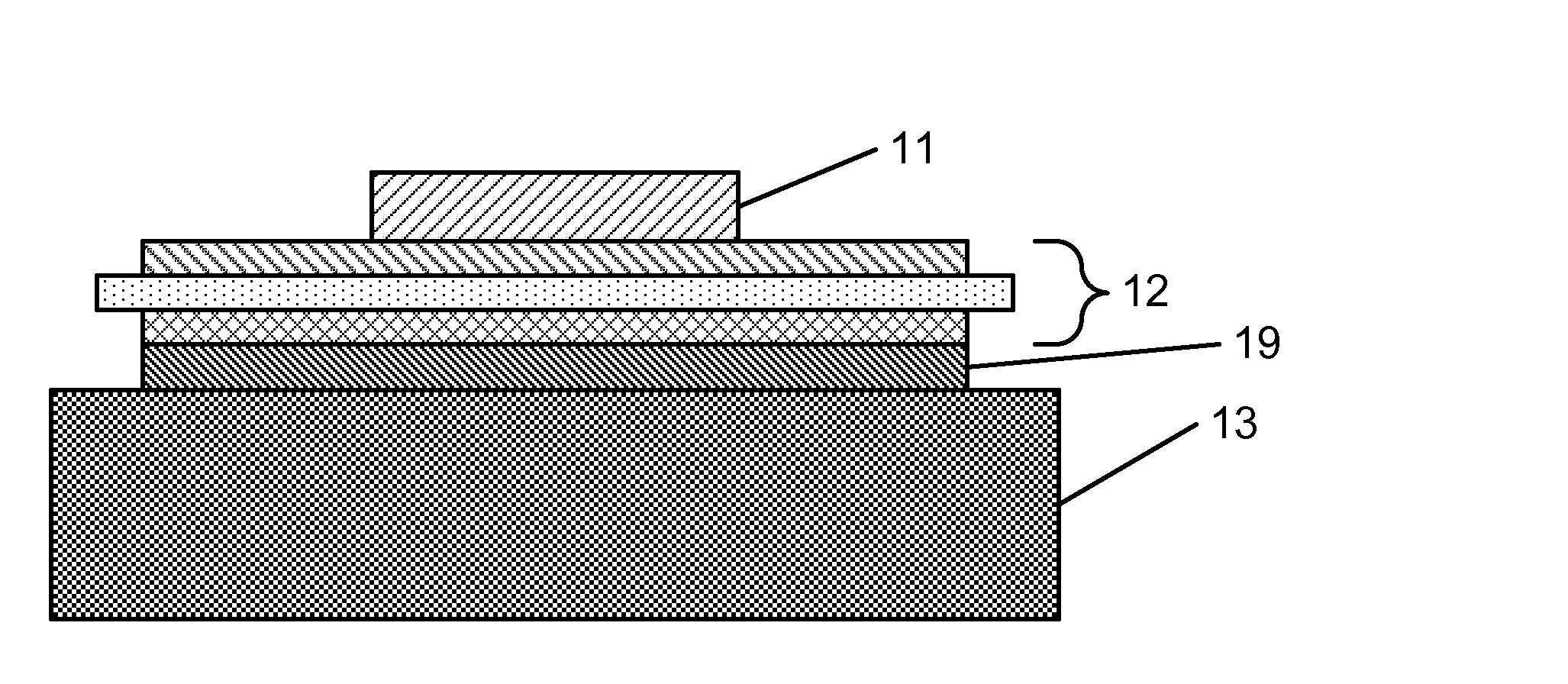
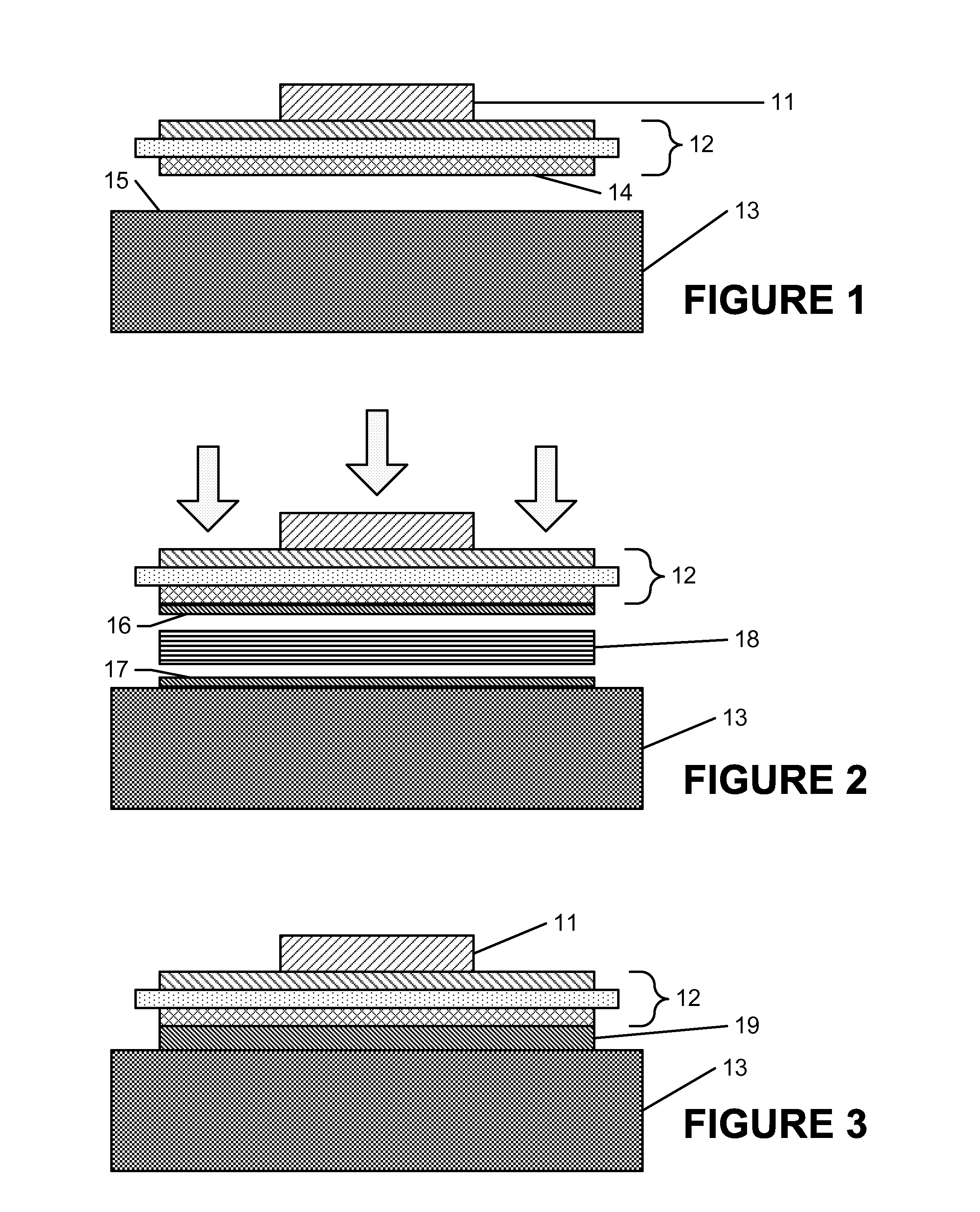
[0028]A heat sink 13 is placed on a hot plate, and a layer of tin solder 17 is applied on the faying (joining) surface 15. The heat sink 13 is then cooled and the tin solder 17 is machined flat to a thickness of 200 μm. The faying surface of receiver module 12 is electroplated with tin to a thickness of 100 μm. A single piece 18 of Ni—Al reactive multilayer foil 60 μm thick is cut to the shape of the bond area (14, 15) and placed between the faying surfaces 14, 15 of the receiver module 12 and heat sink 13. A compliant layer and an aluminum spacer 1.25″ (3.2 cm) thick are placed above the receiver module. A pressure of 200 psi (1.4 MPa) is applied to urge the faying surfaces 14, 15 together. The reactive multilayer foil piece 18 is ignited at an edge and reacts across the bond area to melt a fraction of the solder layers 16 and 17. When the solder 16 and 17 solidify, the receiver module 12 and heat sink 13 are bonded together. The reactive multilayer foil piece 18 may consist of mor...
example 2
[0029]In a second example, both the faying surfaces 14 and 15 of the receiver substrate 12 and heat sink 13 are grit-blasted to a surface finish of between 120 and 800 μin (3-20 μm). The faying surfaces 14, 15 are then coated with a layer of tin 500 μm thick using wire arc spray. The tin layer is subsequently machined to a thickness of 150 μm on each component. A single piece 18 of Ni—Al reactive multilayer reactive foil 60 μm thick is cut to the shape of the bond area and placed between the faying surfaces 14, 15 of the receiver module 12 and heat sink 13. A pressure of 200 psi (1.4 MPa) is applied to urge the faying surfaces 14, 15 together. The reactive multilayer foil piece 18 is ignited at an edge and reacts across the bond area to melt a fraction of the solder. When the solder solidifies, the receiver module and heat sink are bonded together.
[0030]Example 3
[0031]In a third example, the faying surface 15 of heat sink 13 is grit-blasted to a surface finish of between 120 and 800...
PUM
| Property | Measurement | Unit |
|---|---|---|
| Time | aaaaa | aaaaa |
| Surface roughness | aaaaa | aaaaa |
| Surface roughness | aaaaa | aaaaa |
Abstract
Description
Claims
Application Information
 - R&D
- Intellectual Property
- Life Sciences
- Materials
- Tech Scout
- Unparalleled Data Quality
- Higher Quality Content
- 60% Fewer Hallucinations
Browse by: Latest US Patents, China's latest patents, Technical Efficacy Thesaurus, Application Domain, Technology Topic, Popular Technical Reports.
© 2025 PatSnap. All rights reserved.Legal|Privacy policy|Modern Slavery Act Transparency Statement|Sitemap|About US| Contact US: help@patsnap.com