Room temperature crosslinked foam

a cross-linked foam and room temperature technology, applied in the field of spray foams, can solve the problems of difficulty in breathing, rise in the level of moisture and air pollutants, and the conventional spray foams, and achieve the effects of improving cell structure, and reducing the risk of contamination

Active Publication Date: 2010-07-15
OWENS CORNING INTELLECTUAL CAPITAL LLC
View PDF99 Cites 41 Cited by
  • Summary
  • Abstract
  • Description
  • Claims
  • Application Information

AI Technical Summary

Benefits of technology

[0033]It is an advantage of the present invention that the inventive foams do not contain the harmful chemicals found in conventional polyurethane spray foams, such as, for example, MDI monomers. As a result, the foams of the present invention do not contain harmful vapors that may cause skin or lung sensitization or generate toxic waste. Additionally, the foams do not emit harmful vapors into the air when the foam is sprayed, such as when filling cavities to seal and/or insulate a building. The inventive foams are safe for workers to install and, therefore, can be used both in the house renovation market and in occupied houses. Additionally, because there are no harmful chemicals in the inventive foams, the foams can be safely disposed without having to follow any stringent hazardous waste disposal precautions.
[0034]It is another advantage of the present invention that the foams may be applied using existing spray equipment designed for conventional two-part spray polyurethane foam systems without clogging the spray equipment. Thus, the applicat...

Problems solved by technology

There are several problems associated with conventional polyurethane spray foams.
As a result, the levels of moisture and air pollutants rise in these tightly sealed buildings that no longer permit moisture penetration into the building.
Another problem associated with conventional polyurethane spray foams is that the first component (the “A” side) contains high levels of methylene-diphenyl-di-isocyanate (MDI) monomers.
Even a brief exposure to isocyanate monomers may cause diffi...

Method used


Image

  • Room temperature crosslinked foam
  • Room temperature crosslinked foam
  • Room temperature crosslinked foam

Examples


example 1

[0119]Table 1 sets forth a list of components that may be used to make at least one exemplary embodiment of the inventive foam.

TABLE 1Trade NameDescriptionManufacturerFunctionalizedLatexOmnapel 6110Carboxylated AcrylicOmnova Solutions, Inc.LatexNovaCryl PSP 170Carboxylated AcrylicOmnova Solutions, Inc.LatexGenFloCarboxylated SBR LatexOmnova Solutions, Inc.Non-FunctionalizedLatexAcryGen DV300Acrylic LatexOmnova Solutions, Inc.Vycar 660x144Acrylic LatexNoveonF-6694SBR LatexOmnova Solutions, Inc.CrosslinkingAgentsXAMA 7MultifunctionalBayer ChemicalAziridineLindride 56MethylhexahydrophthalicLindau ChemicalAnhydrideHardner CDCarbodiimideRotta Corp.YDH 184CycloaliphaticThai EpoxyDiepoxideBlowing AgentsSodium Bicarbonate / AldrichCitric AcidSodium Carbonate / AldrichCitric AcidCalcium Carbonate / AldrichSodium Bicarbonate / Citric AcidSodium Bicarbonate / Solvay / Rohm&HaasPolyacrylic AcidSurfactantG-5M TritonNon-ionic SurfactantDow ChemicalABEXNon-ionic SurfactantRhodiaStanfax 234Sodium Lauryl Sulfat...

example 2

Determination of Air Leakage

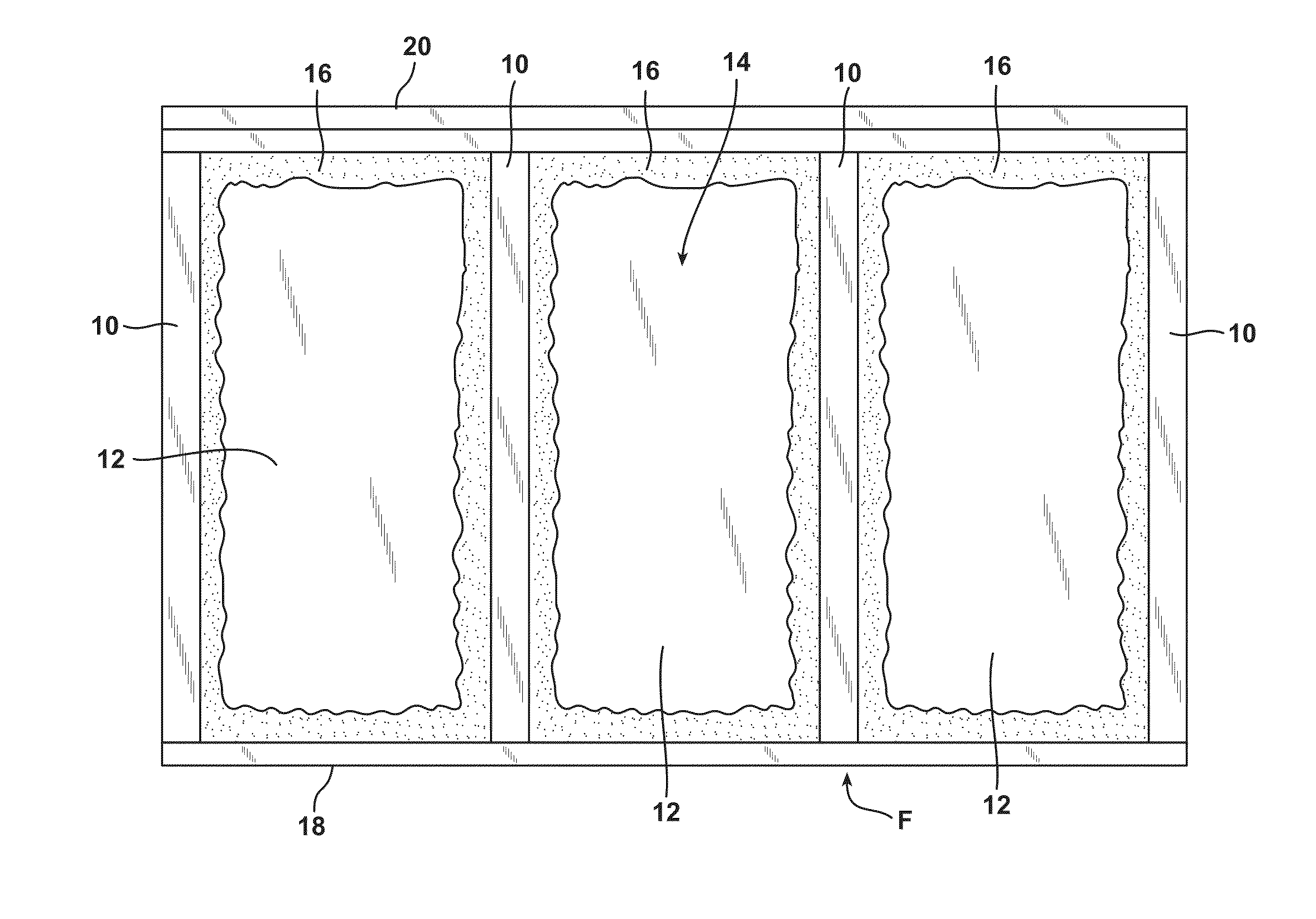
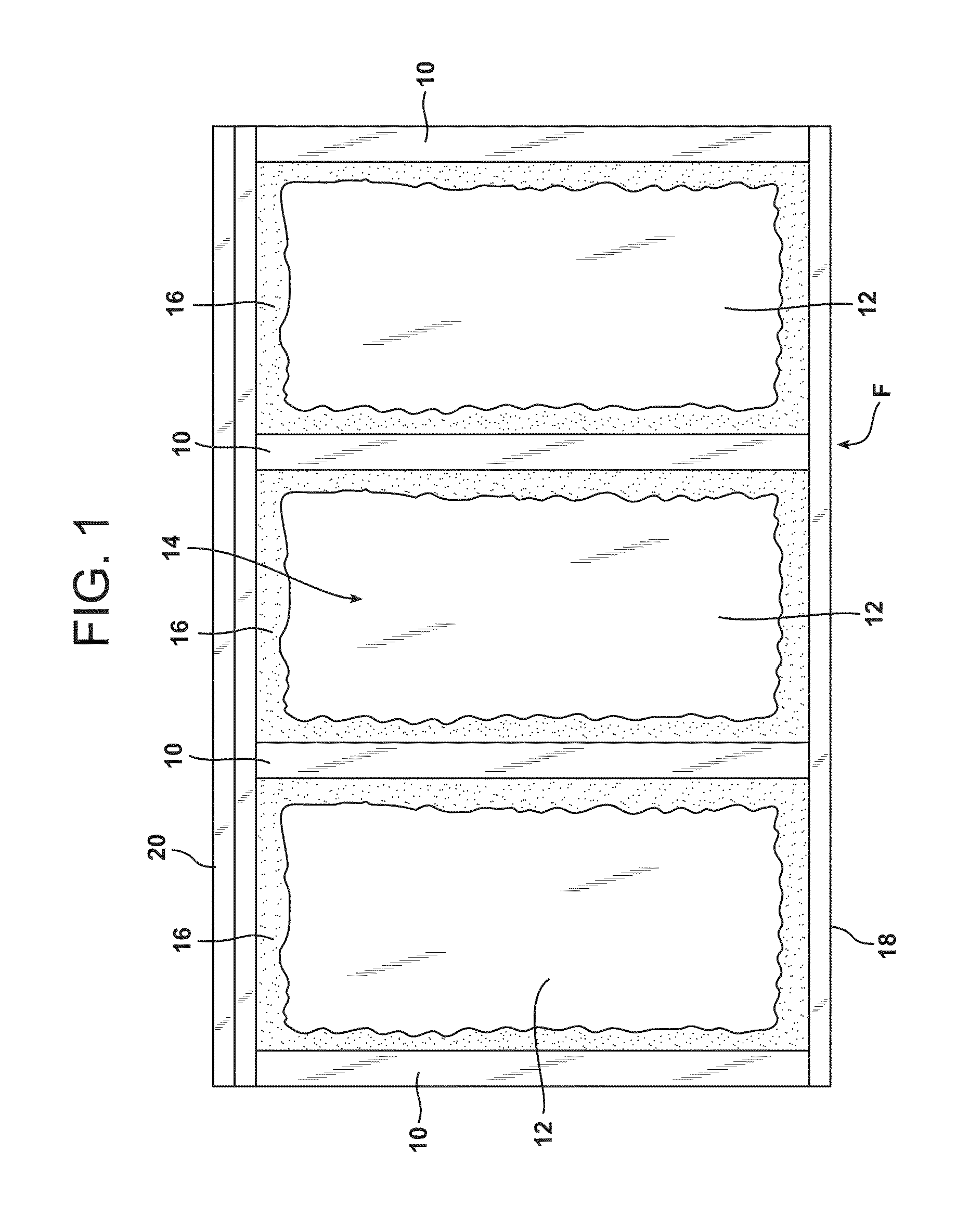
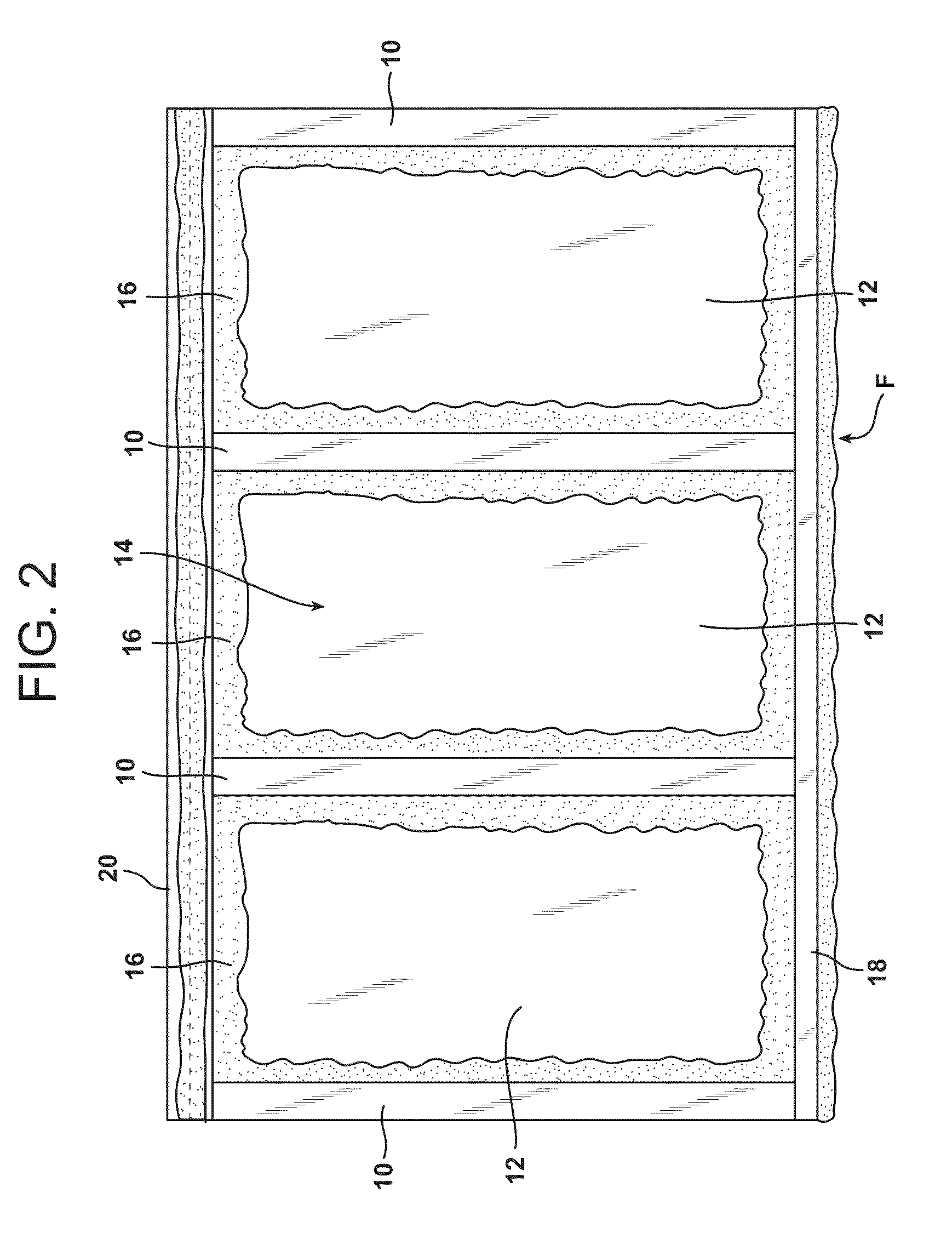
[0125]Various wall structures were tested for air leakage according to the standards set forth in ASTM E283, which is hereby incorporated herein by reference in its entirety. The framed structures were formed of conventional framing studs spaced 16 inches apart externally walled with sheathing formed of oriented strand boards, similar to that illustrated in FIG. 2. The various iterations of the sample wall structures and air leakage results for each are set forth in Table 5.

TABLE 5Air LeakageAir LeakageWall StructureSCFM @ 75 PaNo Inventive Foam UtilizedWall without sealant, no seams taped37.1aWall without sealant, seam taped37.1aWall without sealant, seam taped, window37.1acoveredWall insulated and drywalled26.5Wall Sealed with Inventive FoamWall sealed with inventive foam and window8.4frame foamedWall sealed with inventive foam, insulation8.9positioned in cavity, and drywall affixed tostudsWall sealed with inventive foam and scraped9.4off surface, no in...

example 3

Rate of Rise of Foam Containing Sodium Bicarbonate

[0127]A foam according to the present invention was prepared according to the procedure set forth above. In particular, a first component containing a functionalized resin (i.e., a carboxylated acrylic latex) and an acid (i.e., polyacrylic acid) and a second component containing a room temperature crosslinking agent (i.e., a polyfunctional aziridine) and sodium bicarbonate were mixed and the components were permitted to react to form a foam. The foam was permitted to rise to a 700 ml expansion. In one sample, the sodium bicarbonate had a mean particle size of 50 microns. In the second sample, the sodium bicarbonate had a mean particle size of 11 microns. The results are set forth in Table 6.

TABLE 6Rate of Rise Due To Sodium BicarbonateSize of Sodium BicarbonateTime(microns)(seconds)11285050

[0128]As shown in Table 6, the sodium bicarbonate with a mean particle size of 11 microns reached a 700 ml expansion in 28 seconds. The foam sampl...


PUM

PropertyMeasurementUnit
Particle sizeaaaaaaaaaa
Sizeaaaaaaaaaa
Sizeaaaaaaaaaa

Abstract

Low rise, user friendly latex foams for sealing insulative cavities of a building are provided. The foams may be applied to the interface of the sheathing and the studs within the insulative cavities to reduce air leaks. The latex foams may also be applied to the face of the studs to obtain an additional seal against air infiltration. The foam can be used to affix fiberglass batts, batt flanges, and vapor barriers to the framing without mechanical fasteners. A tackifier may be added to impart an adhesive quality to the foam. The tacky nature of the foam permits the drywall or vapor barrier to be repositioned without damage. Drywall is held onto the face of the studs by the tacky foam while mechanical fasteners are inserted to permanently affix the drywall to the framing. The compressive nature of the foam permits drywall to be attached without significant bowing or detachment.

Description

CROSS-REFERENCE TO RELATED APPLICATIONS[0001]This application is a continuation-in-part of U.S. patent application Ser. No. 11 / 647,747, entitled “Spray-In Latex Foam For Sealing And Insulating” filed on Dec. 29, 2006, a continuation-in-part of U.S. patent application Ser. No. 11 / 893,451 entitled “Room Temperature Crosslinked Foam” filed on Aug. 16, 2007, a continuation-in-part of U.S. patent application Ser. No. 11 / 893,474 entitled “Room Temperature Crosslinked Foam” filed on Aug. 16, 2007, a continuation-in-part of U.S. patent application Ser. No. 11 / 893,436 entitled “Room Temperature Crosslinked Foam” filed on Aug. 16, 2007, a continuation-in-part of U.S. patent application Ser. No. 11 / 893,435 entitled “Room Temperature Crosslinked Foam” filed on Aug. 16, 2007, and a continuation-in-part of U.S. patent application Ser. No. 11 / 977,849 entitled “Room Temperature Crosslinked Material” filed on Oct. 25, 2007, the entire content of each are expressly incorporated herein by reference in...

Claims


Application Information

Patent Timeline
IPC IPC(8): E04B2/02B05D1/02
CPCC08F265/04E04F21/085C08J9/12C08J2207/02C08J2321/00C08K3/0033C08L33/02C08L33/06C08L51/003C08L51/04C08L53/02C08L53/025C09J151/003C09J151/04C09J153/02E04B1/7604C08J9/08C08L21/02C08L2666/04C08L2666/02C08K3/013
Inventor KORWIN-EDSON, MICHELLE L.OLANG, FATEMEH N.O'LEARY, ROBERT J.
Owner OWENS CORNING INTELLECTUAL CAPITAL LLC
Why Eureka
Try Eureka