Device For Control of Difficult to Compress Hemorrhage

a hemorrhage and hemorrhage technology, applied in the field of hemorrhage control devices, can solve the problems of high incidence of penetrating injuries to the extremities and their associated mortality, and achieves the effects of preventing bleeding, low cost and portability, and small footprin

Active Publication Date: 2010-07-15
VIRGINIA COMMONWEALTH UNIV
View PDF44 Cites 66 Cited by
  • Summary
  • Abstract
  • Description
  • Claims
  • Application Information

AI Technical Summary

Benefits of technology

[0013]The present invention provides a portable, compact device that can be used to selectively exert pressure on areas of the body of an injured individual where it is otherwise difficult to do so. In particular, the device may be used to stop bleeding from difficult areas such as the groin, pelvis and abdomen. The device is low-cost and portable, has a small footprint, and can be readily and ra

Problems solved by technology

Hemorrhage from vascular injuries in the proximal extremities, pelvis, and abdomen is extremely difficult to treat.
While the treatment of such injuries is challenging when they occur in civilian populations, they are even more difficult to treat in combat situations.
While improvements in body armor have reduced mortality from combat injuries to the chest, the incidence of penetrating injuries to the extremity and their associated mortality remain high.
Clearly, wounds to the groin, pelvis, and abdomen are complex and may involve several systems either alone or in combination, including major vascular structures, the bony pelvis, solid organs such as the liver and spleen, and even hollow organ injury to the bowel and bladder.
Wounds directly involving isolated major vascular structures above the level of the femoral artery and vein such as the iliac artery and veins are most challenging to deal with followed by complex bony pelvic injuries from high velocity penetrating trauma resulting in complex arterial and lower pressure venous bleeding similar to those of blunt pelvic injuries experienced in a civilian trauma center.
Lastly even injuries involving isolated major vascular injury at or just above the inguinal ligament pose a tremendous field challenge in creating hemostasis.
Despite this, the ability to control bleeding by application of direct pressure by either the injured combatant or by others including fellow soldiers or medic aides will usually not suffice especially if rapid manual transport must take place.
Controlling hemorrhage by application

Method used


Image

  • Device For Control of Difficult to Compress Hemorrhage
  • Device For Control of Difficult to Compress Hemorrhage
  • Device For Control of Difficult to Compress Hemorrhage

Examples


example 1

Reduction and Elimination of Blood Flow in Femoral Artery

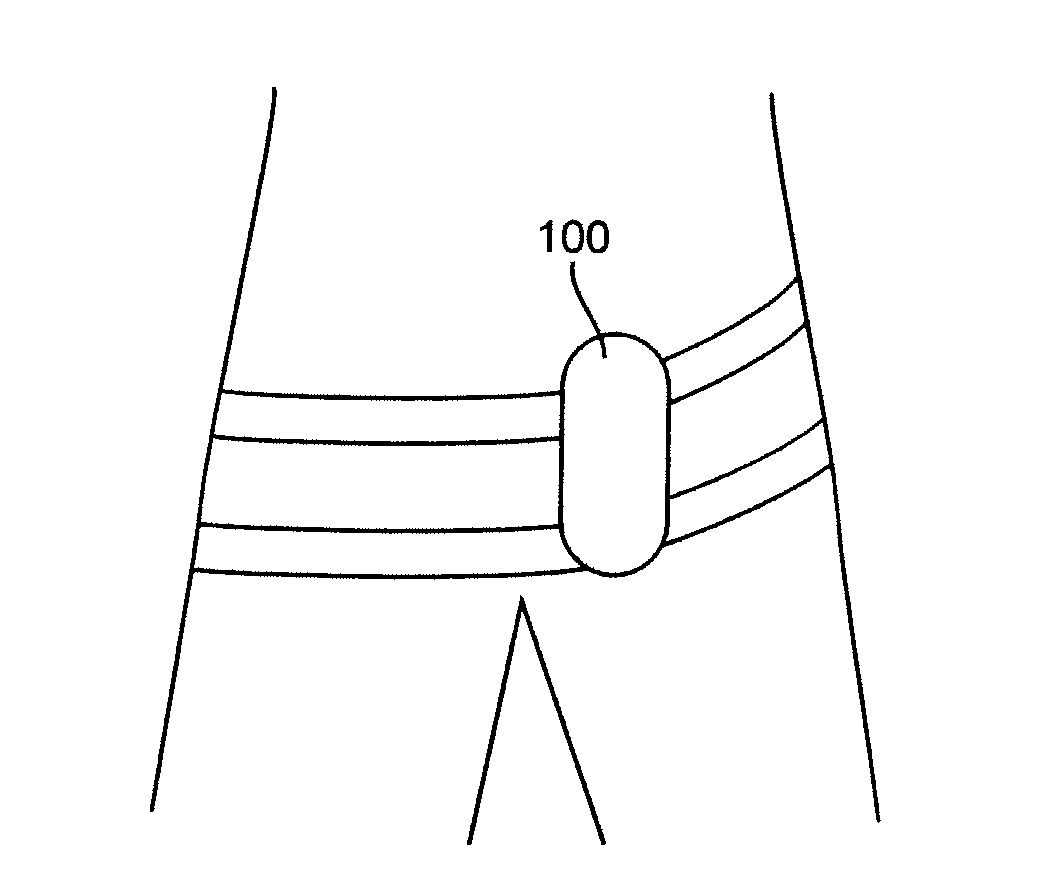
[0063]The prototype device of the invention depicted in FIG. 8A was attached to a human subject so that the inflatable bladders rested against the groin, as illustrated schematically in FIG. 7A. One inflatable bladder was inflated to approximately 300 mmHg using hand bulb pump mechanisms; inflation pressure was monitored using an aneroid manometer. The flow of blood through the femoral arteries was monitored using Doppler ultrasoundphotoplethysmography.

[0064]The results of applying pressure on the region of the left femoral artery is depicted in FIGS. 8B and C, where blood flow is shown in the insets and pulsatile blood flow is shown in the lower trace prior to (FIG. 8B) and after (FIG. 8C) the application of pressure by bladder inflation. As can be seen, FIG. 8C shows no blood flow in the inset and the elimination of pulsatile flow in the trace below after inflation of the bladder. These effects were reproducible in both femo...

example 2

In Vivo Demonstration of Hemorrhage Control

[0065]A 40 kg swine was previously instrumented with an abdominal aortic flow probe which measures blood flow going through the abdominal as it exits below the diaphragm. The animal is also instrumented with an arterial catheter in the carotid artery to measure arterial blood pressure and a central venous catheter is placed into the superior vena cava via the external jugular vein to measure central venous pressure (CVP).

[0066]The compression device of the invention was placed around the closed abdomen and snuggly secured. Baseline readings were taken at 13:45. The device was rapidly inflated causing the inflatable members to expand downward towards and in toward the abdominal wall, thereby directing pressure into the abdominal cavity. Hemodynamic measurements were taken from 13:45:30 to 13:47:30 and the results are presented in Table 1. The results demonstrate significant reductions abdominal aortic blood flow with a simultaneous increase ...

example 3

In Vivo Demonstration of Usefulness of the Apparatus as an Adjunct to CPR

[0068]In this example, a 40 kg swine was instrumented as described in Example 2 above. However, the device of the invention was place around the animal's chest. A state of cardiopulmonary arrest was produced by injection of potassium chloride while the animal was anesthetized with alpha choralose. Various parameters were measured as in Example 2, and are presented in Table 2.

TABLE 2Time 13:53:18Time 13:56:00DeflatedInflatedArterial32mmHgArterial45mmHg23mmHg40mmHgCVP8.4mmHgCVP9.5mmHg7.2mmHg8.4mmHgAortic Flow0Aortic Flow0.14ml / min00.17ml / minCPP15.8mmHgCPP31.6mmHgTime 13:54:00Time 13:56:30InflatedDeflatedArterial49mmHgArterial17.6mmHg41mmHg12.8mmHgCVP9.7mmHgCVP6.6mmHg8.5mmHg6.3mmHgAortic Flow0.37ml / minAortic Flow0.01ml / min0.07ml / min0.01ml / minCPP32.5mmHgCPP6.5mmHg

[0069]Time 13:53:18 shows hemodynamic parameters after cardiac arrest with only ventilation with a mechanical ventilator at a tidal volume of 10 cc / kg and...


PUM


Abstract

Bleeding from blood vessels located in difficult-to-compress regions of the body (especially the abdomen, pelvic or groin region) is controlled by the use of a portable, small-footprint belt-like device that contains multiple inflatable bladders. The inflatable bladders are selectively positioned and inflated over exsanguinating blood vessels, thereby exerting pressure to stop the bleeding. The device may also be used to provide perfusion support in low flow disease states such as hemorrhagic shock and cardiac arrest.

Description

BACKGROUND OF THE INVENTION[0001]1. Field of the Invention[0002]The invention generally relates to controlling bleeding from severed or damaged peripheral blood vessels that are located in an area where it is difficult to apply conventional compression, such as the abdomen, pelvic or groin region. In particular, the invention provides a portable, small-footprint device with inflatable bladders that can be selectively positioned and inflated to exert pressure over peripheral blood vessels to stop exsanguination. In addition, the device may be used to assist in increasing perfusion pressure to the heart and brain in a number of disease sates such as hemorrhagic shock, cardiogenic shock, and cardiac arrest.[0003]2. Background of the Invention[0004]Hemorrhage from vascular injuries in the proximal extremities, pelvis, and abdomen is extremely difficult to treat. While the treatment of such injuries is challenging when they occur in civilian populations, they are even more difficult to t...

Claims


Application Information

Patent Timeline
IPC IPC(8): A61B17/135A61B17/12
CPCA61B17/1325A61B17/1322A61B17/135A61B17/12A61B2017/12004
Inventor WARD, KEVIN R.LICATA, MARK
Owner VIRGINIA COMMONWEALTH UNIV
Why Eureka
Try Eureka