Fluid delivery systems, devices and methods for delivery of hazardous fluids

a technology of fluid delivery system and hazardous fluid, which is applied in the direction of packaging foodstuffs, packaging goods, and therapy, etc., can solve the problems of requiring that the doctor manipulate the fluid path, carries some risk of operator error, and takes time to manipulate, so as to facilitate the operation and ensure the safety of the patient. , the effect of ensuring the safety of the patien

Inactive Publication Date: 2010-07-22
BAYER HEALTHCARE LLC
View PDF45 Cites 63 Cited by
  • Summary
  • Abstract
  • Description
  • Claims
  • Application Information

AI Technical Summary

Benefits of technology

[0031]In one embodiment of the system of the present invention, the container is a vessel in which the hazardous pharmaceutical is distributed by a manufacturer. The container can enclose sufficient hazardous pharmaceutical for delivery to multiple patients. In another embodiment, the container is filled with the hazardous pharmaceutical using a loading device that maintains biohazardous materials containment. Once again, the filled container can enclose sufficient hazardous pharmaceutical for delivery to multiple patients.
[0048]The systems, devices and methods of the present invention can be used with X-ray, MR, CT, ultrasound or other medical imaging modalities, and can beneficially inject many fluids and types of fluids in addition to gene therapy drugs.

Problems solved by technology

A difficulty with such currently available injection devices is the requirement that the doctor manipulate the fluid path, sometimes having to disconnect the manual contrast injection syringe and connect the thrombolytic injector.
This manipulation takes time, and carries some risk of operator error, including inadvertent biological contamination.
There are a number of drawbacks or unmet needs with the current systems and processes for gene therapy delivery.
Furthermore, disconnecting and reconnecting multiple syringes for delivering contrast, saline, and drugs is time consuming and increases the risk that some of the drug may be spilled or aerosolized and thus infect the operator and / or the patient in an undesired fashion, or that the drug may be contaminated.
Moreover, it is very difficult for a human to inject a fluid at a steady rate, especially for slow rates (ml / min) extending more than a minute.
Motion at a slow rate suffers from stick-slip friction in the syringe, and it takes significant concentration to do it for two 1-2 minute periods up to five times in a procedure.
There is significant risk of accidental jerking or bolus injection that either wastes drug or causes it to reflux into the aorta and travel elsewhere in the body.
Also, as syringes are connected and disconnected, the plunger can be unintentionally bumped and a bolus of drug injected into the patient or expelled into the environment.
Additionally, the changeover time from drug syringe to saline syringe causes an uncontrolled break in therapy injection.
As the drug is susceptible to clump formation if agitated, manually connecting and disconnecting the syringe provides opportunities for agitation and clumping.
However, such catheter placement introduces the risk of reducing blood flow through that artery and increases the possibly of causing dissections.
Moreover, deep sub-selective catheter placement is more difficult technically to achieve.
Multiple manual manipulations of syringes and the manifold connected to the catheter in the patient increases the risk that the catheter position will be accidentally shifted from optimum placement.
Multiple manual manipulations also increases the risk of errors, such as injecting saline first, and then the drug, and thus having the drug in the catheter being injected into the aorta when it is being moved from one vessel to another.
Similarly, aerosolization or spillage of chemotherapy agents during preparation or delivery can create hazardous conditions for health care workers or nearby people.
It has the downside of requiring the occupation of the expensive facilities of a catheterization or special procedures suite.
The making and breaking of connections provides the opportunity for drug spillage or aerosolization and thus transmission to nearby personnel.
With intra-venous administration, many chemotherapy agents damage the veins in which they are injected.
This causes local reactions and pain, and it makes it difficult for health care workers to subsequently be able to insert a catheter into the vein.
Each time the needle is removed from one site and moved to another there is the opportunity for aerosolization and / or spillage since the drug is present at the needle tip.
In this case, the drug is intentionally delivered as an aerosol of a liquid or a power, so the problem is particularly severe.
Thus there is a significant amount of aerosol that could be accidentally released.

Method used


Image

  • Fluid delivery systems, devices and methods for delivery of hazardous fluids
  • Fluid delivery systems, devices and methods for delivery of hazardous fluids
  • Fluid delivery systems, devices and methods for delivery of hazardous fluids

Examples


Embodiment Construction

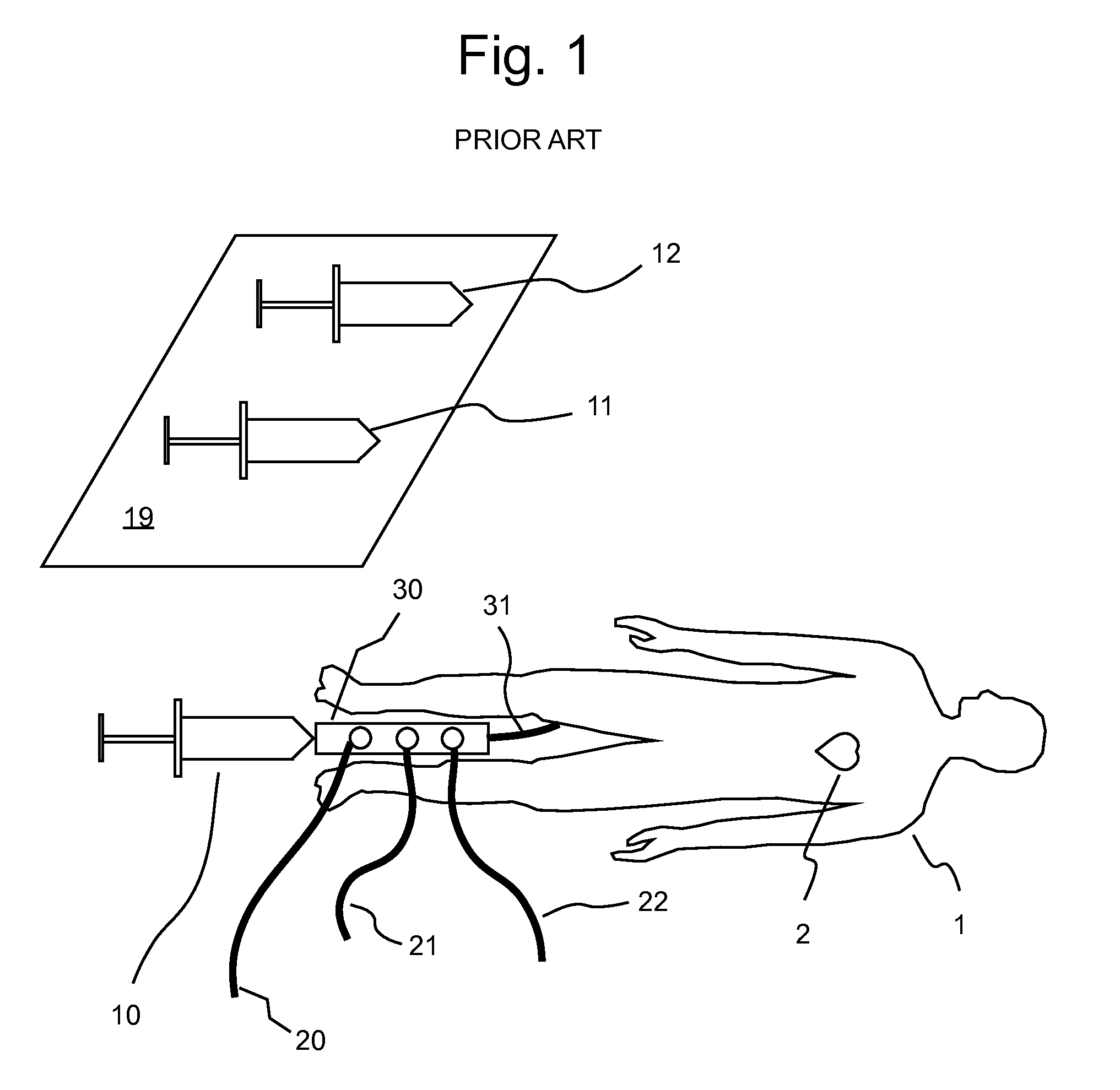
[0072]A system currently used for the injection of a gene therapy drug is illustrated in FIG. 1. In FIG. 1, a patient 1 has a catheter 31 inserted via a femoral (leg) artery into the arteries nourishing the patient's heart 2. A number of catheters with single or dual side-by-side lumens are commonly used. The catheters can have just an end hole, or multiple side holes to increase the mixing of the drug with the blood. An infusion catheter slid inside a guiding catheter is also commonly used. Other arteries can be used for accesses as well. The external end of a catheter 31 is connected via a connector to a manifold 30, either directly or with an intermediate piece of tubing (not shown). Other common angiographic equipment and personnel such as a guide wire, a hemostasis valve, an X-ray imaging system, an MR imaging system, an ultrasound imaging system, or other imaging equipment, as well as physicians and nurses are not shown in FIG. 1.

[0073]Manifold 30 has several valves, typically...


PUM

PropertyMeasurementUnit
pressuresaaaaaaaaaa
volumesaaaaaaaaaa
flexibleaaaaaaaaaa

Abstract

A system for injecting a patient, includes a container enclosing a hazardous pharmaceutical; a first pump to deliver a hazardous pharmaceutical to a patient and a fluid path operably connected to the first pump, the container, and the patient. The system further includes a hazardous material containment suitable to confine the hazardous pharmaceutical during connection of the hazardous pharmaceutical container to the fluid path.

Description

CROSS-REFERENCE TO RELATED APPLICATION[0001]This application is a divisional of U.S. patent application Ser. No. 10 / 821,210, filed Apr. 8, 2004, now patented, and claims the benefit of U.S. Provisional Patent Application Ser. No. 60 / 461,152, filed Apr. 8, 2003, the disclosures of which are incorporated herein by reference.BACKGROUND OF THE INVENTION[0002]The present invention relates generally to fluid delivery systems, to fluid delivery devices and to methods of fluid delivery, and, especially, to fluid delivery systems of hazardous medical fluids, devices for use therein and to methods of delivering hazardous medical fluids to a patient. Current angiographic practice uses X-ray imaging to visualize the inside of the body. Physicians deftly maneuver catheters to a desired blood vessel. X-ray absorbing contrast is injected so that the vessel and downstream vessels can be clearly seen on the X-ray display or film. Using the resultant image, a physician makes a diagnosis and determine...

Claims


Application Information

Patent Timeline
Patent Type & Authority Applications(United States)
IPC IPC(8): A61M36/08A61M5/31A61MA61M5/00A61M5/14A61M31/00
CPCA61M5/007A61M5/1408A61M5/1452A61M2202/049A61J1/2096A61M5/142A61M5/44A61N5/1001A61M25/0045
Inventor UBER, III, ARTHUR E.HIRSCHMAN, ALAN D.GRIFFITHS, DAVID M.TROMBLEY, FREDERICK W.REILLY, DAVID M.
Owner BAYER HEALTHCARE LLC
Why Eureka
Try Eureka