Intravascular Blood Filter

a blood filter and intravascular technology, applied in the field of medical devices, can solve the problems of tissue ischemia (lack of oxygen and nutrients), morbidity and mortality, loss of limbs, stroke, etc., and achieve the effect of limiting potential entanglemen

Active Publication Date: 2010-07-22
BOSTON SCI SCIMED INC
View PDF99 Cites 75 Cited by
  • Summary
  • Abstract
  • Description
  • Claims
  • Application Information

AI Technical Summary

Benefits of technology

[0015]One method of filtering the carotid arteries leaving the aorta free from obstruction is to deliver a filter to each of the carotid arteries from the groin leaving them in the carotid vasculature and retrieving them via snare post procedure. A delivery catheter would be inserted through an introducer in the groin (femoral artery) and delivered to the common carotid arteries and detached. The delivery catheter would be removed and a second filter would be delivered in a similar manner to the other carotid artery. With two detached filters now in place the procedure treating the aortic or mitral valve can now be completed with embolic protection for the cerebral vascular system. Once the procedure to the valve is completed, the filters can be snared and retrieved back out the femoral artery as they were delivered. Any embolic particles will be captured in the filter device and removed safely from the body.
[0016]Another method for filtering the carotid arteries would be to deliver a filter from the femoral artery and utilize a single catheter to house the two attachment means to the filters. These attachments may be a wire similar to a guidewire or a hypo-tube to connect the filter element to an external portion of the body. Keeping these wires or connection means organized and contained within a single or dual lumen catheter will help organize and limit potential entanglement with other catheters being delivered to the target site such as the aortic valve or other cardiac elements including but not limited to the mitral valve and coronary arteries. The distal portion of the catheter may have a single exit portion or a staggered exit to allow an exit at different points along the catheter. One exit port may be at the distal most end of the catheter and the other may be a centimeter proximal from this to allow the attachment wire to exit near the left common carotid artery. Furthermore, there could be an extension to the distal most portion of the catheter allowing side ports for both wires to exit. This would allow for additional catheter stabilization within the aorta.

Problems solved by technology

These disorders are a major cause of morbidity and mortality in the United States and throughout the world.
When an artery is occluded by a clot, tissue ischemia (lack of oxygen and nutrients) develops.
Failure to reestablish blood-flow can lead to the loss of limb, angina pectoris, myocardial infarction, stroke, or even death.
Occlusion of the venous circulation by thrombi leads to blood stasis which can cause numerous problems.
While such surgical techniques have been useful, exposing a patient to surgery may be traumatic and is best avoided when possible.
Additionally, the use of a Fogarty catheter may be problematic due to the possible risk of damaging the interior lining of the vessel as the catheter is being withdrawn.
Balloon angioplasty is appropriate for treating vessel stenosis but is generally not effective for treating acute thromboembolisms.
Unfortunately, thrombolysis typically takes hours to days to be successful.
Additionally, thrombolytic agents can cause hemorrhage and in many patients the agents cannot be used at all.
Another problematic area is the removal of foreign bodies.
The use of such removal devices can be difficult and sometimes unsuccessful.
Moreover, systems heretofore disclosed in the art are generally limited by size compatibility and the increase in vessel size as the emboli is drawn out from the distal vascular occlusion location to a more proximal location near the heart.
If the embolectomy device is too large for the vessel it will not deploy correctly to capture the clot or foreign body, and if too small in diameter it cannot capture clots or foreign bodies across the entire cross section of the blood vessel.
Additionally, if the embolectomy device is too small in retaining volume then as the device is retracted the excess material being removed can spill out and be carried by flow back to occlude another distal vessel.
However, such devices have been found to have structures which are either highly complex or lacking in sufficient retaining structure.
Disadvantages associated with the devices having highly complex structure include difficulty in manufacturability as well as difficulty in use in conjunction with microcatheters.

Method used


Image

  • Intravascular Blood Filter
  • Intravascular Blood Filter
  • Intravascular Blood Filter

Examples


Embodiment Construction

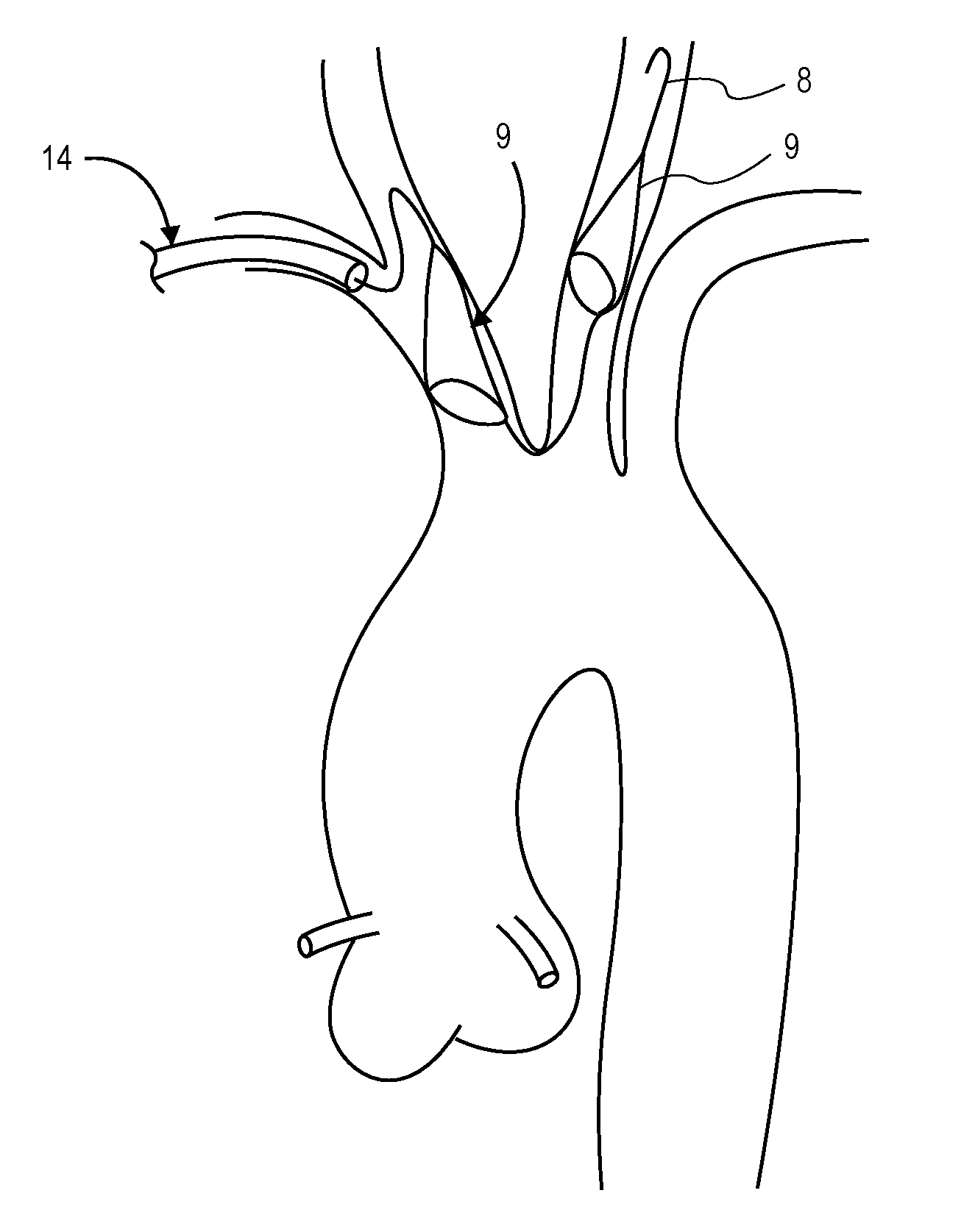
[0041]Before standard intervention would occur by a cardiologist a filter would be placed into the carotid arteries to protect the circulation to the brain where emboli could induce a stroke and leave the patient debilitated. Placement of these filters to the patient's carotid circulation would be most convenient if it occurred without obstruction of the aorta where other catheters would be passed and preferably on the patient's right side as it is common practice for the doctor to steer the catheters from this side of the table. Standard practice is to gain access in the right femoral artery where a sheath would be placed to introduce catheters, guidewires and other device delivery means. This would leave the left femoral artery open but often it too is used for other diagnostic catheters and it is less convenient to work across the patient's body. Other access sites would include carotid entry but the neck area is often again inconvenient to operate from and generally too far from...


PUM


Abstract

Disclosed is a novel filter and delivery means. The device described within will not interfere with standard practice and tools used during standard surgical procedures and tools such as cannulas, clamps or dissection instruments including valve replacement sizing gages or other surgical procedures where the patient must be put on a heart-lung machine cross-clamping the aorta.

Description

CROSS-REFERENCE TO RELATED APPLICATIONS[0001]This application claims the benefit of U.S. Provisional Application No. 61 / 145,149, filed Jan. 16, 2009, entitled “Intravascular Blood Filter,” the disclosure of which is incorporated herein by reference.INCORPORATION BY REFERENCE[0002]All publications and patent applications mentioned in this specification are herein incorporated by reference to the same extent as if each individual publication or patent application was specifically and individually indicated to be incorporated by reference.BACKGROUND OF THE INVENTION[0003]This invention relates generally to medical devices used during vascular intervention, and more particularly, concerns medical devices that are useful in treating aortic valve replacement, thromboembolic disorders and for removal of foreign bodies in the vascular system.[0004]Thromboembolic disorders, such as stroke, pulmonary embolism, peripheral thrombosis, atherosclerosis, and the like, affect many people. These dis...

Claims


Application Information

Patent Timeline
Patent Type & Authority Applications(United States)
IPC IPC(8): A61F2/01
CPCA61F2/01A61F2/013A61F2002/018A61F2230/0069A61F2230/0008A61F2230/0067A61F2230/0006A61F2/012
Inventor LASHINSKI, RANDALL T.
Owner BOSTON SCI SCIMED INC
Why Eureka
Try Eureka