
Projection exposure apparatus and projection exposure method

a technology of projection exposure and projection exposure, which is applied in the field of projection exposure apparatus and projection exposure method, can solve the problems of uniformity deterioration, image of mask pattern cannot be uniformly formed, and predetermined pattern with sufficient accuracy cannot be formed in all the areas, so as to reduce the non-uniformity of light intensity distribution

Inactive Publication Date: 2010-08-05
TOKYO DENKI UNIVERSITY
View PDF3 Cites 31 Cited by
  • Summary
  • Abstract
  • Description
  • Claims
  • Application Information

AI Technical Summary

Benefits of technology

[0025]The present invention intends to solve the problems that such a conventional constitution has had, and it aims at achieving a projection exposure apparatus and a projection exposure method capable of reducing the non-uniformity of the light intensity distribution within the irradiation area, and forming a pattern finer than previous one, in which a line width change of the transcriptional pattern is small to the same mask pattern line width and the sidewall is smooth.

Problems solved by technology

However, even in the projection exposure of the same magnification using the aforementioned gradient refractive index lens array of the conventional art, the image of the mask pattern cannot be uniformly formed only by simply using the gradient refractive index lens array.
Additionally, since the uniformity deteriorates due to manufacturing error of the lens element, pitch error of the array, flatness error of the end surface, or the like, the light intensity distribution in the irradiation area will also be in a nonuniform state.
The non-uniformity may appear in the light intensity distribution as described above, and thus when a fine pattern with the minimum line width of about 2 to 100 micrometers is projected as in the case of the semiconductor manufacturing or the liquid crystal panel manufacturing, predetermined patterns with sufficient accuracy cannot be formed in all the areas within a field where the scanning exposure is performed due to the influence of this non-uniformity, only by simply using the gradient refractive index lens array for scanning in the direction perpendicular to the arrangement of the lens elements to allow the mask pattern to be projected.

Method used


Image

  • Projection exposure apparatus and projection exposure method
  • Projection exposure apparatus and projection exposure method
  • Projection exposure apparatus and projection exposure method

Examples


examples

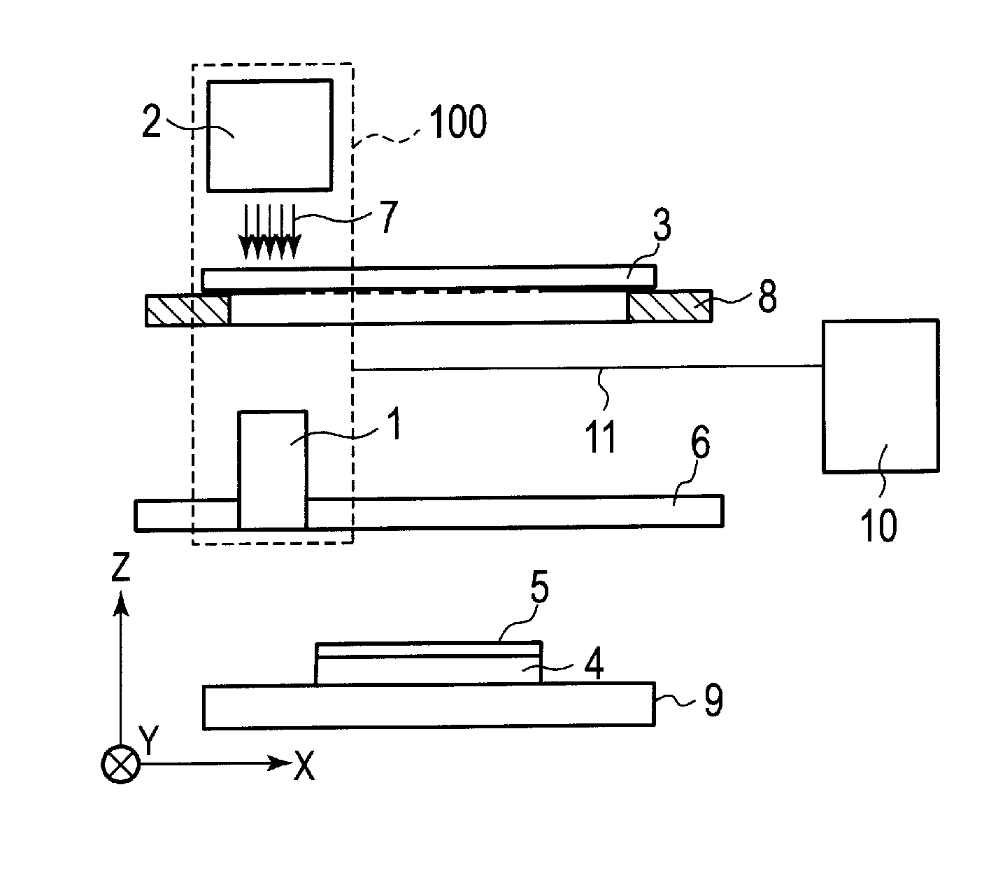
[0134]The projection exposure apparatus of the configuration shown in FIG. 5 of the first embodiment of the present invention could be achieved by using SLA (SELFOC lens array) made by Nippon Sheet Glass Co., Ltd. in which a diameter and the number of lines of the lens element are 1.1 millimeters and 2, respectively as the gradient refractive index lens array 1, a halogen lamp made by Sumita Optical Glass, Inc. as the illuminating device 2, and a notebook PC as the computer 10.

[0135]While the gradient refractive index lens array 1 used for the experiment has resolution performance capable of forming a line and space with a line width of 5 to 10 micrometers on an exposed substrate in which a positive resist made by TOKYO OHKA KOGYO CO., LTD. is coated on a silicon wafer at a film thickness of 1 micrometer when projection exposure is performed while keeping it to stand still, it has a size of about 195 millimeters in width, about 5 millimeters in thickness, and about 16 millimeters in...


PUM


Abstract

Exposure areas are wholly overlapped by moving a gradient refractive index lens array in a direction perpendicular to a scanning direction, or by providing a plurality of gradient refractive index lens arrays, an optical filter having a density distribution of lightness and darkness to compensate light transmission nonuniformity of the gradient refractive index lens array is arranged, or an opening control plate for limitedly using only of a uniform portion is provided. Two or more means may be simultaneously provided among the aforementioned mean. Moreover, any one of a microscopic transmission shutter array, a microscopic reflection shutter array, and a microscopic light emitter array is used instead of a mask, or an illuminating device and the mask.

Description

TECHNICAL FIELD[0001]The present invention relates to a projection exposure apparatus and a projection exposure method for replicating a fine pattern of a display, a semiconductor integrated circuit, an optoelectronics device, a micromachine part, or the like on a large area exposed substrate such as a large sized glass substrate, a plastic substrate, a plastic substrate with copper foil, and a screen for screen-printing, a metal sheet, or a large-diameter wafer.BACKGROUND ART[0002]Exposure is used for replicating a pattern of a mask onto a photosensitive material, such as a photoresist formed on an exposed substrate, in which a mask on which the pattern is formed by depositing a shielding material, such as chromium, on a transparent substrate such as glass and then etching it, and short wavelength visible light, ultraviolet rays, deep ultraviolet rays, or the like are then irradiated on the exposed substrate through the mask. A process of selectively leaving only an exposed portion...

Claims


Application Information

Patent Timeline
Patent Type & Authority Applications(United States)
IPC IPC(8): G03B27/72
CPCG02B3/0056G02B3/0087G02B26/02G02B26/0875G03F7/70558G03F7/70275G03F7/70291G03F7/70466G03F7/70191
Inventor HORIUCHI, TOSHIYUKIKOBAYASHI, HIROSHI
Owner TOKYO DENKI UNIVERSITY
Features
  • Generate Ideas
  • Intellectual Property
  • Life Sciences
  • Materials
  • Tech Scout
  • Unparalleled Data Quality
  • Higher Quality Content
  • 60% Fewer Hallucinations
Learn More