Microfluidic device

a microfluidic and device technology, applied in the direction of material analysis, positive displacement liquid engine, optical light guide, etc., can solve the problems of preventing further progress in the rapid analysis device and the structure of these components is often complex

Inactive Publication Date: 2010-08-26
BRUNEL UNIVERSITY
View PDF2 Cites 41 Cited by
  • Summary
  • Abstract
  • Description
  • Claims
  • Application Information

AI Technical Summary

Benefits of technology

[0003]The main advantages of μ-TAS over traditional devices lie in lower fabrication costs, improvement of analytical performance regarding quality and operation time, small size, disposability, precise detection, minimal human interference and lower power consumption. Moreover, the problem of rare chemical and samples which restrain the application of genetic typing and other molecular analyses has been resolved by employment of μ-TAS.
[0008]It is an object of the current invention to provide a microfluidic device which provides improved mixing of liquids, for example in a microchannel, or chamber and also provides simpler fabrication and which overcomes or mitigates the problems of the prior art particularly coagulation of whole blood samples.SUMMARY OF THE INVENTION
[0018]The inventors have found that the elliptical configuration of the teeth of the device result in a magnetic field which is more evenly distributed about the tooth, as compared to other shapes of tooth, such as triangular, where the magnetic field is only stronger at the tip.
[0020]It will be apparent to the skilled person that the device may also include a high permeable (e.g permalloy) layer located within or adjacent the first and / or third layers distal to the microchannel to increase the magnetic field generated by the device.
[0022]It has been found that when device is in use, this region acts to increase the rate at which a sample liquid can be mixed. This is of particular use where the sample is a liquid which is liable to thicken or coagulate, for example whole blood. The use of blood as the sample is of particular interest in devices which are designed as home use or point of care use, because the sample can be easily obtained by a simple needle prick.
[0056]As mentioned above, the elliptical configuration of the teeth of the device result in a magnetic field which is more evenly distributed about the tooth, as opposed to other shapes of tooth, such as triangular, where the magnetic field is stronger only at the tip. This results in greater mixing due to chaotic movement of the beads.

Problems solved by technology

Due to the complexity of the sample preparation, most available biochip systems still perform this initial step off-chip using traditional bench-top methods.
As a result, rapid developments in back-end detection platforms have shifted the bottleneck, impeding further progress in rapid analysis devices, to front-end sample preparation where the “real” samples are used.
A problem with the currently known microfluidic devices is performing efficient chaotic mixing in these platforms, this usually needs existence of moving parts, obstacles, grooves, and twisted or three dimensional serpentine channels.
The structures of these components tend to be complex, however, requiring complicated fabrication processes such as multi-layer stacking or multi-step photolithography.

Method used


Image

  • Microfluidic device
  • Microfluidic device
  • Microfluidic device

Examples


Embodiment Construction

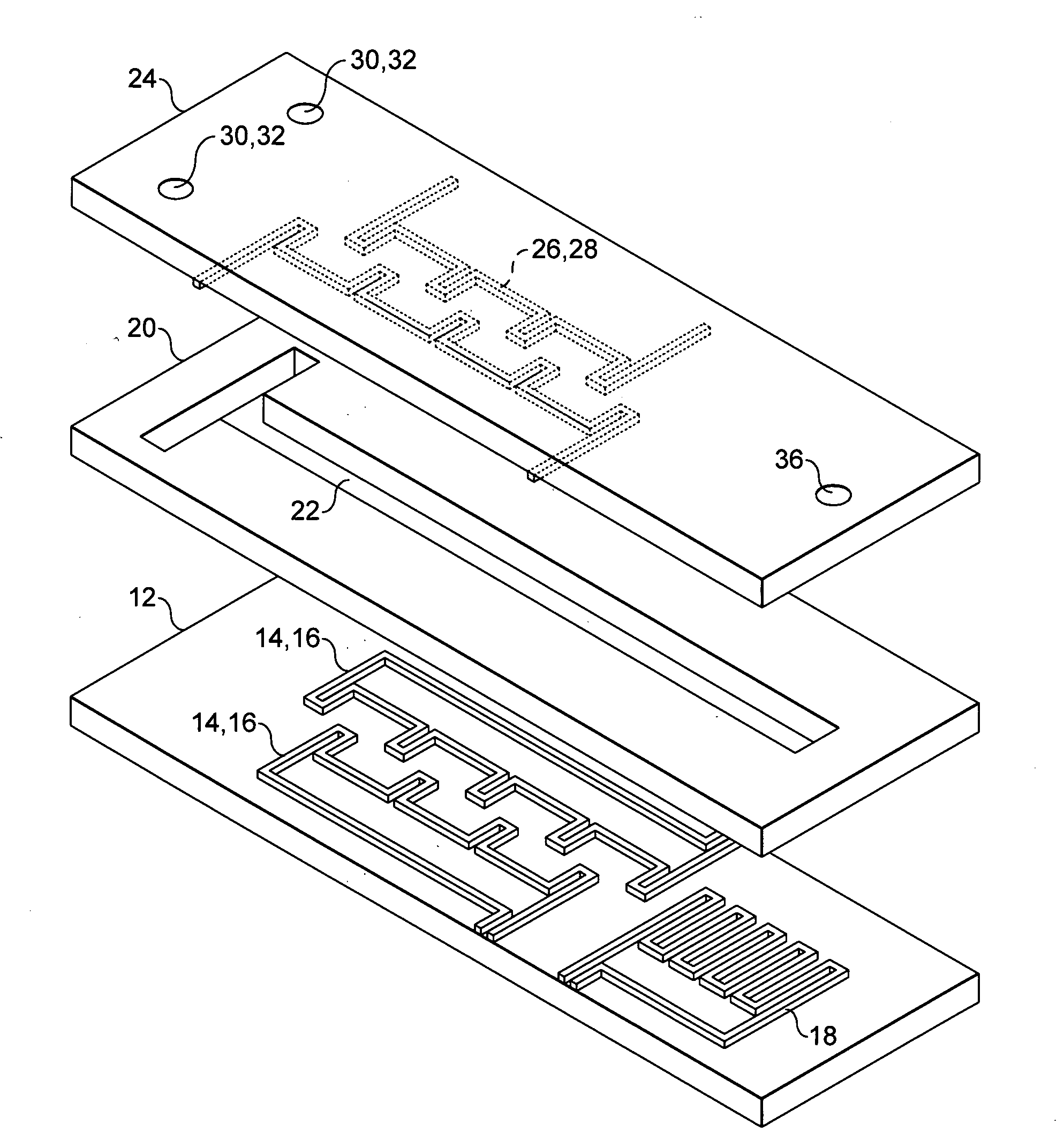
[0112]The micromixer 10, as shown in FIG. 1 comprises a base layer 12 formed from glass having three serpentine conductors 14, 16, 18 embedded therein. A central layer 20 formed from PDMS comprising a straight channel 22 which is located above the serpentine conductors 14, 16, 18 and a upper layer 24 formed from glass having two further serpentine conductors 26, 28 embedded therein, two inlet ports 30, 32 and an outlet port 36.

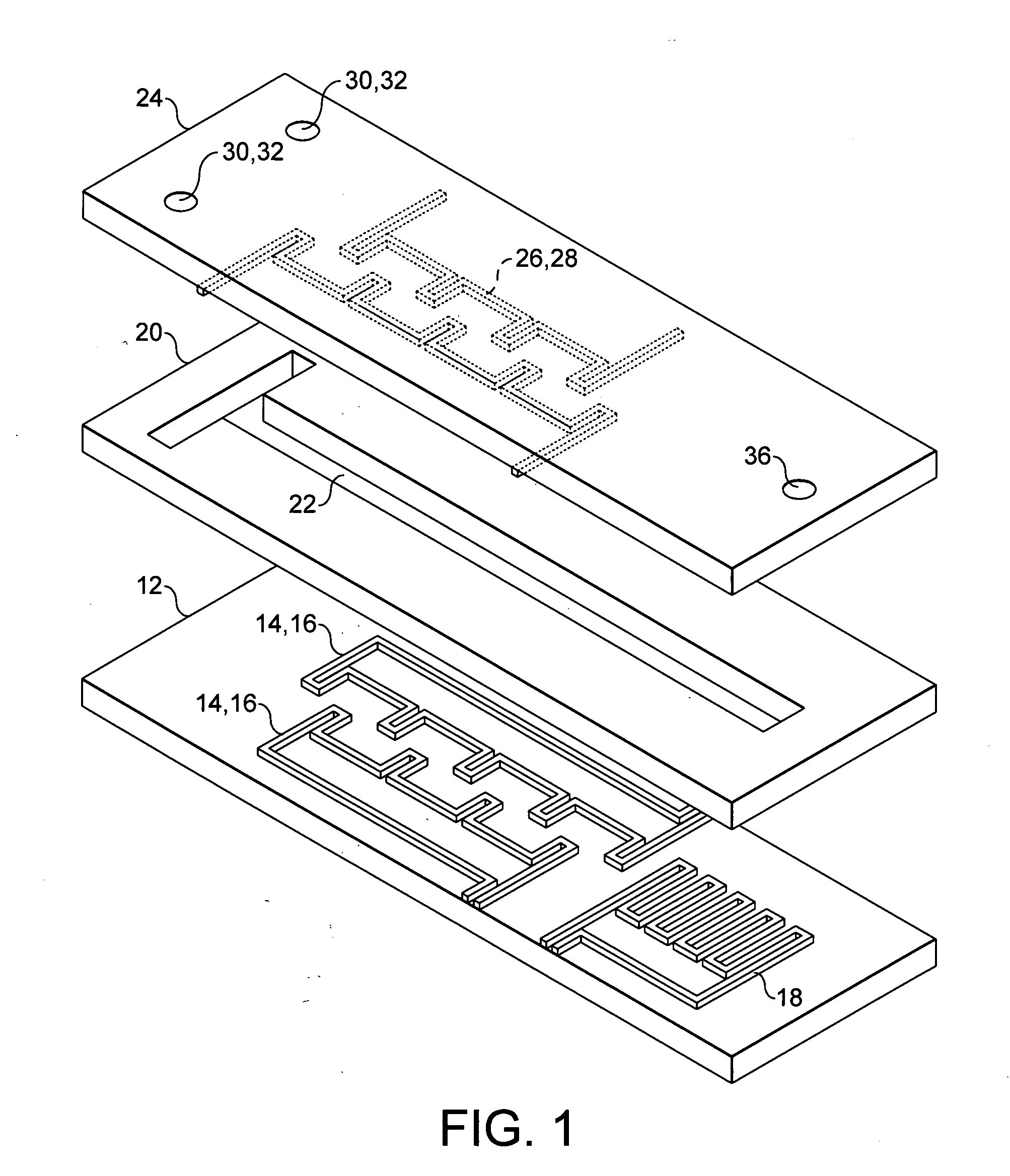
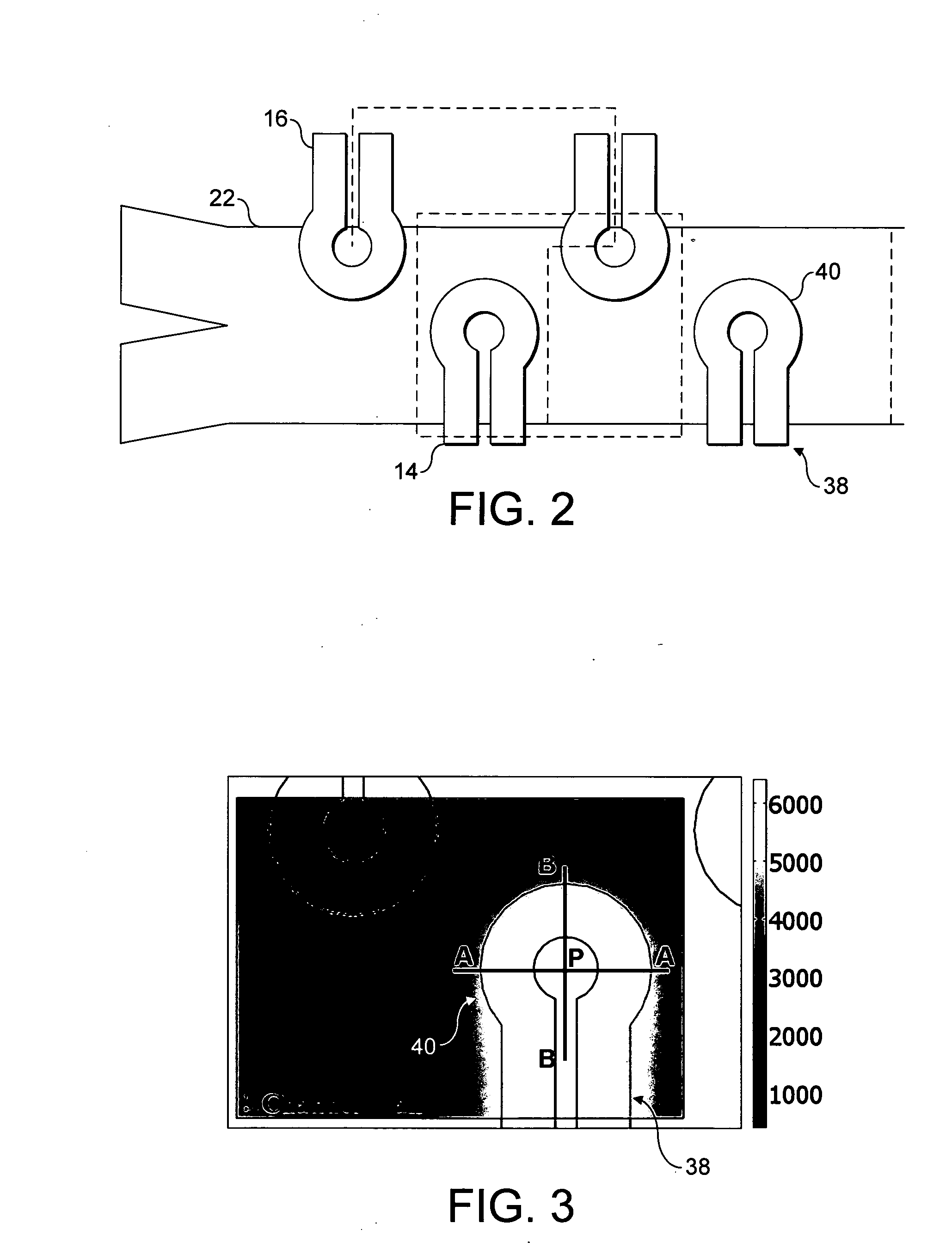
[0113]An example of the dimensions of the device are shown in FIG. 2 where a top-view of one mixing unit with its boundaries is illustrated. Each mixing unit comprises two adjacent teeth from each conductor. Channel 22 is 150 μm wide and 50 μm deep. Conductors 14, 16 are in the shape of teeth 38 having circular tips 40 and are 35 μm high and 35 μm wide in the section and distances between centres of circular tips 40 of the conductors are 100 μm and 65 μm in x and y directions, respectively. Each row of upper and lower conductors 14, 16 is connected to the powe...


PUM

PropertyMeasurementUnit
diameteraaaaaaaaaa
currentaaaaaaaaaa
currentaaaaaaaaaa

Abstract

A microfluidic device comprising; i) an inlet; ii) a first layer comprising at least first and second current carrying structures, wherein the at least first and second current carrying structures each comprise a plurality of teeth, and wherein the teeth of the first and second current carrying structures are optionally offset such that the teeth of the first current carrying structure are positioned between the teeth of the second current carrying structure; iii) a second layer comprising a first microfluidic chamber in fluid communication with the inlet positioned above the at least first and second current carrying structures of the first layer; and iv) a third layer comprising at least third and fourth current carrying structures wherein the at least third and fourth current carrying structures each comprise a plurality of teeth, and wherein the teeth of the third and fourth current carrying structures are optionally offset such that the teeth of the third current carrying structure are positioned between the teeth of the fourth current carrying structure; and wherein the at least third and fourth current carrying structures are positioned in the third layer so as to be above the first microfluidic chamber and such that the teeth of the third current carrying structure are positioned substantially vertically above or offset from the teeth of the first current carrying structure and the teeth of the fourth current carrying structure are positioned substantially vertically above or offset from the teeth of the second current carrying structure; wherein the teeth have a stem having substantially elliptical tip.

Description

SUMMARY[0001]The current invention relates to a microfluidic device and to methods of its use for isolating and detecting an analyte from a biological sample.INTRODUCTION[0002]Over the past decade, the advent of Micro-Electro-Mechanical Systems (MEMS) which is based on the miniaturization of mechanical components and their integration with micro-electrical systems, has created the potential to fabricate various structures and devices on the order of micrometers. This technology takes advantage of almost the same fabrication techniques, equipment and materials that were developed by semi-conductor industries. The range of MEMS applications is growing significantly and is mainly in the area of micro-sensors and micro-actuators. In recent years, miniaturization and integration of bio-chemical analysis systems to MEMS devices has been of great interest which has led to invention of Micro Total Analysis Systems (μ-TAS) or Lab-on-a-Chip (LOC) systems.[0003]The main advantages of μ-TAS ove...

Claims


Application Information

Patent Timeline
Patent Type & Authority Applications(United States)
IPC IPC(8): C12Q1/68B81B7/02G01N33/50G01N1/28G01N1/34C12M1/00
CPCB01F13/0059B01F13/0818B01L3/50273B01L3/502746B01L3/502761Y10T436/25B01L2300/0645B01L2300/0809B01L2300/087B01L2400/043B01L2200/0647B01F33/30B01F33/452G01N27/44791B01F33/3032B01J19/00B01L3/00B01F25/00B01F33/00
Inventor BALACHANDRAN, WAMADEVAAZIMI, SAYYED MOHAMADAHERN, JEREMYZOLGHARNI, MASSOUDBAHMANYAR, MOHAMMAD REZASLIJEPCEVIC, PREDRAG
Owner BRUNEL UNIVERSITY
Why Eureka
Try Eureka