
Implant with high vapor pressure medium

a high-pressure medium and implant technology, applied in the field of medical devices, to achieve the effect of facilitating the rehabilitation of the neuromuscular system, increasing the outlet resistance, and restoring continen

Inactive Publication Date: 2010-09-02
SOLACE THERAPEUTICS
View PDF100 Cites 179 Cited by
  • Summary
  • Abstract
  • Description
  • Claims
  • Application Information

AI Technical Summary

Benefits of technology

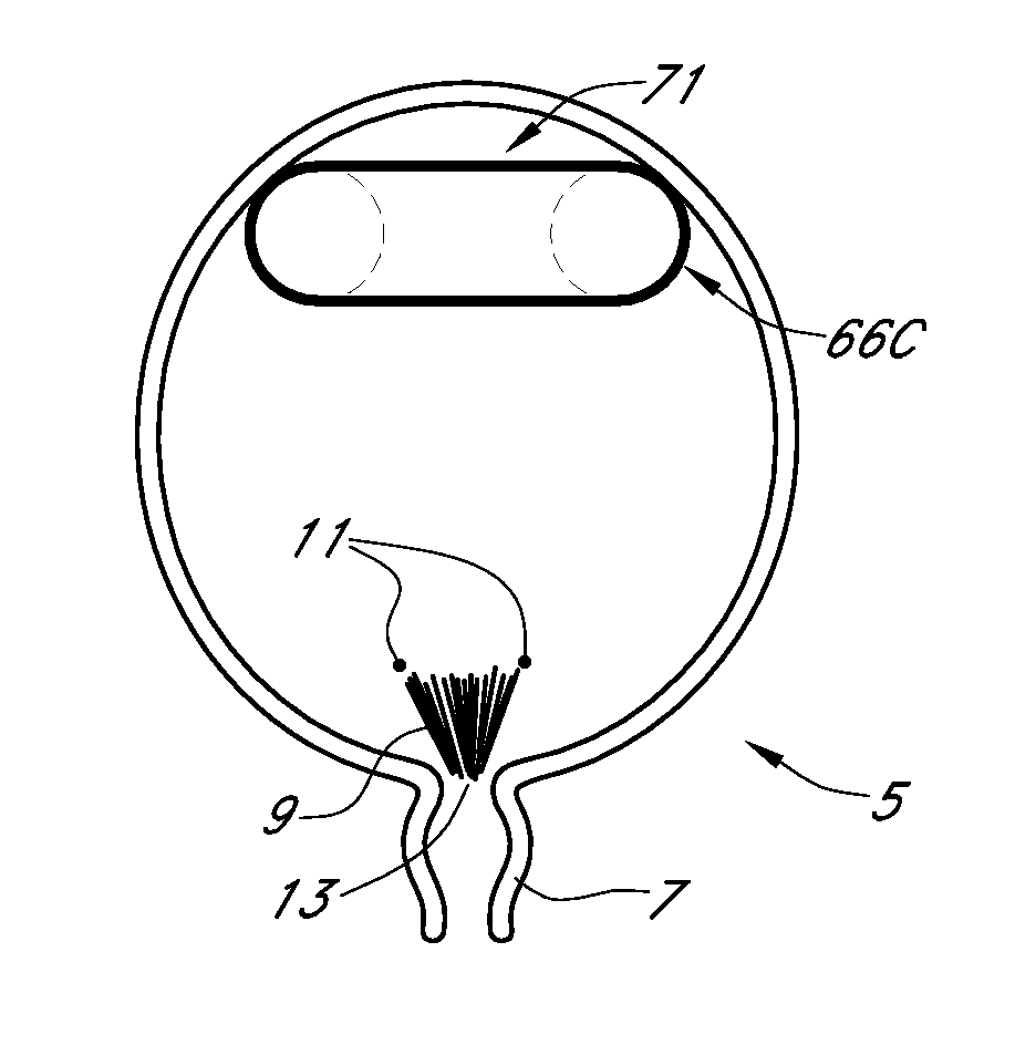
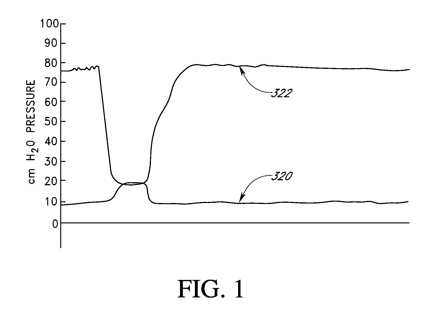
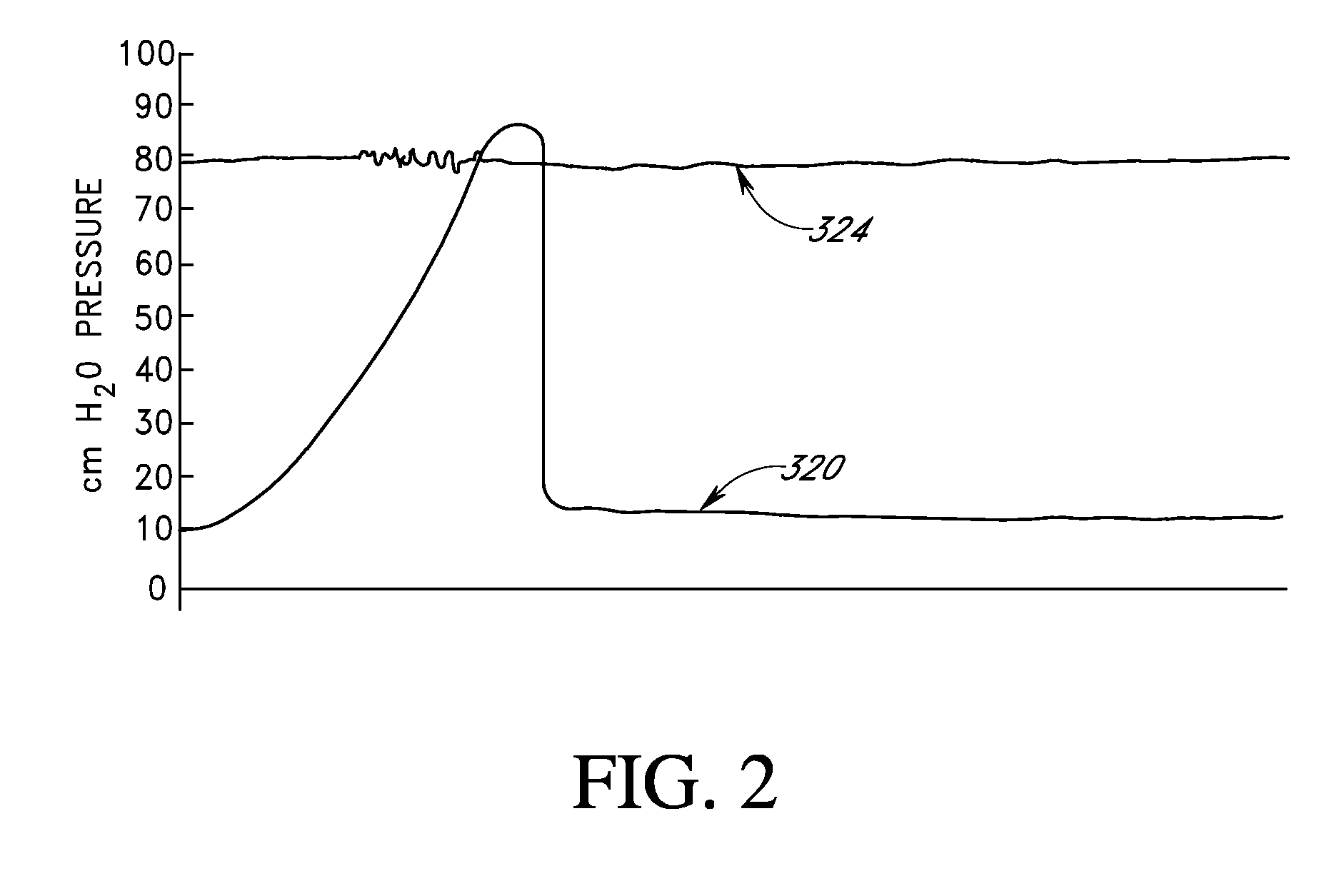
[0024]In some embodiments a method of preventing stress urinary incontinence can comprise the steps of: providing a pressurized implant operable to reversibly occupy intravesical space in response to a pressure increase event to impede the rate of an intravesical pressure increase event during an initial period of around 0 milliseconds to 1 second of said event thereby allowing time for neurological signaling of a guarding reflex to increase the outlet resistance of an external urinary sphincter sufficient to prevent leakage of urine through said sphincter after said initial period; and implanting said device within said bladder, the device configured for a selected treatment period. The selected treatment period can also facilitate rehabilitation of a neuromuscular system of the bladder and restoration of continence.
[0025]Some embodiments involve a pre-packaged system for preventing the diffusion of PFC out of an implant or the inflation of the implant prior to implantation. The system can comprise a relatively gas impermeable package; a gas permeable inflatable implant comprising an enclosure, said implant residing in said package; a first portion of PFC within the enclosure in the implant; and a second portion of PFC within the package and around the implant. The implant can be sealed off from exposure to the environment until said package is breached thereby maintaining the first portion of PFC within said implant and maintaining an implant volume within the sealed package.
[0029]In addition to creating space, an implant can also be used to decrease space. For example, a method according to certain embodiments can comprise performing a first medical procedure in a region inside a body, wherein a space is created by the removal of material; advancing an expandable implant into the space in a first configuration; inserting a media into an enclosure within the expandable implant, wherein the media comprises at least one PFC; expanding the expandable implant to a second configuration to fill the space, wherein the implant is fully self-contained within the space; and reducing the size of the space. In some embodiments of the method, the at least one PFC can comprises two PFCs, the first having a higher vapor pressure than the second and / or reducing the size of the space can comprise reducing the size of the implant from the second configuration to a third configuration.

Problems solved by technology

An example of a problem where there is a need for improved medical devices and methods is dealing with pressure events in the body.
These pressure events have many undesirable effects ranging from discomfort, to stress on the organs and tissue, to fluid leakage such as urinary incontinence, to renal failure, stroke, atherosclerosis, heart attack and blindness.

Method used


Image

  • Implant with high vapor pressure medium
  • Implant with high vapor pressure medium
  • Implant with high vapor pressure medium

Examples


example 1

[0408]In one illustrative embodiment, intraocular implants or other implantable devices described herein comprise a silicone elastomer, polyolefin or acrylic balloon that may be used to contain air and the selected PFC vapor. The balloons may range in volume from 0.1 milliliters to 2 milliliters.

[0409]The eye is a challenging environment in which to deliver and maintain the inflation of a therapeutic implant because the intraocular pressure exceeds atmospheric pressure and the oxygen tension in the anterior and posterior segments of the eye is known to be significantly less than the oxygen tension in normal atmospheric air. In the absence of a PFC, the balloon will deflate due to the intraocular pressure (IOP) exceeding the oxygen and nitrogen tensions in the anterior and posterior segments of the eye. The oxygen tension in the normal atmosphere is approximately 159 mm of Hg. The oxygen tension in the intraocular environment ranges from 10 to 30 mm of Hg. The nitrogen tension in the...

example 2

[0412]Self-inflation of a balloon in an ophthalmic application can be achieved with a balloon composed of a material which is permeable to oxygen and nitrogen. At the time of implantation, the balloon is charged with the PFC mixture and a minimal amount of air (e.g. 1-25 microliters). The balloon may also be filled with additional air to reduce the time required for complete balloon inflation. Shortly after the time of implantation, the PFC vapor pressure exceeds the IOP in the eye minus the total gas tension in the fluids surrounding the bladder. Self-inflation will occur as a result of diffusion of oxygen and nitrogen, from the vitreous in the case of a posterior segment placement or from the aqueous in the case of an anterior segment placement, through the walls of the balloon as the PFC vapor has diluted these gases, inside the balloon, to partial pressures that are less than their gas tensions in the contacting fluids. The time required for self-inflation will vary from several...

example 3

[0413]To assure that balloon inflation is maintained, the vapor pressure of the PFC mixture may be increased by 1-100 mm Hg relative to the level that matches the IOP / fluid total gas tension differential. In this case the skin tension of the balloon will offset the amount by which the PFC vapor pressure within the balloon exceeds the equilibrium value. The skin tension will pressurize the balloon gases until the oxygen, nitrogen and other gas partial pressures within the balloon rise to match their gas tensions in the contacting fluids. The additional vapor pressure will compensate for normal diurnal fluctuations in IOP.

[0414]For internal balloon gas equilibrium pressures that exceed the IOP, the skin tension of the balloon counterbalances the excess gas equilibrium pressures (defined as equilibrium pressure minus IOP or the PFC vapor pressure plus the total fluid gas tension minus the IOP). The mechanical characteristics of the balloon as well as its polymeric structure are such th...


PUM


Abstract

An implant for use in a human or animal body can include a flexible housing with an outer wall and having a chamber therein. The implant can have at least one high vapor pressure medium within the chamber. The at one high vapor pressure medium can have a combined vapor pressure equal to or greater than about the average value of the hydrostatic pressure of the implantation site plus the skin tension of the housing minus the gas tension of the dissolved gasses present at the implantation site.

Description

[0001]This application is a continuation-in part of U.S. patent application Ser. No. 12 / 343,120 filed Dec. 23, 2008; which is a divisional of U.S. patent application Ser. No. 10 / 391,448 filed Mar. 17, 2003, now U.S. Pat. No. 7,470,228; which is a continuation of U.S. patent application Ser. No. 10 / 391,446, filed Mar. 17, 2003, now U.S. Pat. No. 6,976,950; which claims priority to U.S. Provisional Patent Application Ser. No. 60 / 415,949, filed Oct. 3, 2002; U.S. patent application Ser. No. 10 / 391,446 is also a continuation-in-part of U.S. patent application Ser. No. 09 / 723,309 filed on Nov. 27, 2000, now U.S. Pat. No. 6,682,473; which claims priority to U.S. Provisional Patent Application Ser. No. 60 / 197,095, filed Apr. 14, 2000; this application also claims priority to U.S. Provisional Patent Application Ser. No. 61 / 200,147, filed Nov. 25, 2008; and U.S. Provisional Patent Application Ser. No. 61 / 211,515, filed Mar. 31, 2009; the disclosures of the aforementioned applications are her...

Claims


Application Information

Patent Timeline
IPC IPC(8): A61M29/00
CPCA61F9/00781A61M25/10A61B5/205A61B17/0401A61B17/221A61B17/32056A61B17/3478A61B17/66A61B17/70A61B17/7065A61B17/7098A61B17/82A61B18/1442A61B19/24A61B2017/00539A61B2017/00557A61B2017/00858A61B2017/0435A61B2017/22035A61B2017/22062A61B2017/2215A61F2/0027A61F2/004A61F2/0059A61F2/042A61F2/10A61F2/12A61F2/2481A61F2/26A61F5/0013A61F13/20A61F13/26A61F2002/30617A61F2002/3071A61F2250/0067A61F2250/0068A61F2250/0085A61F2250/0097A61M25/00A61M25/04A61M25/1002A61M2025/0076A61M2025/1054A61M2210/1078A61M2210/1085A61M29/02A61F2250/0059A61B17/00234A61B17/3468A61B1/307A61B90/02
Inventor GILLESPIE, JR., JOHNCONNORS, KEVIN G.SCHUTT, ERNEST G.DAYTON, PETER
Owner SOLACE THERAPEUTICS
Learn More