Biaxial birefringent component, liquid crystal projector, and method for manufacturing biaxial birefringent component

a liquid crystal projector and component technology, applied in the direction of instruments, polarising elements, non-linear optics, etc., can solve the problems of light modulation, affecting the density of black display, and providing a relatively narrow field of view, so as to improve image contrast and low cost manufacturability

Active Publication Date: 2010-09-16
FUJIFILM CORP
View PDF11 Cites 5 Cited by
  • Summary
  • Abstract
  • Description
  • Claims
  • Application Information

AI Technical Summary

Benefits of technology

[0021]According to the present invention, the phase difference caused by tilted liquid crystal molecules in the liquid crystal layer is compensated properly, and image contrast is improved for the liquid crystal projector. The phase compensator is composed of the biaxial birefringent component made by oblique deposition of an inorganic material, and it offers durability and low cost manufacturability.

Problems solved by technology

However, the liquid crystal panels, which act on different liquid crystal modes, can only provide a relatively narrow field-of-view in each liquid crystal mode.
This problem results from the liquid crystal molecules lying near substrates that hold the liquid crystal layer.
As a result, light modulation performance of the TN liquid crystal panel depends on the angle-of-incidence of a light ray to the liquid crystal layer, and affects the density of black display.
When made from a birefringent crystal such as the single crystal sapphire or quartz, a phase compensator becomes durable enough, but high-precision control is required for a cutting surface and thickness of the crystal, making the phase compensator too expensive to use for commercial products.
Conventional oblique deposition films cannot completely compensate the phase difference due to the tilt components.

Method used


Image

  • Biaxial birefringent component, liquid crystal projector, and method for manufacturing biaxial birefringent component
  • Biaxial birefringent component, liquid crystal projector, and method for manufacturing biaxial birefringent component
  • Biaxial birefringent component, liquid crystal projector, and method for manufacturing biaxial birefringent component

Examples


example 1

[0069]Using the oscillating evaporator 60, a ZrO2—TiO2 composition was obliquely deposited onto a base plate of borosilicate glass, at a deposition speed of 0.2 nm per second, so as to form a biaxial birefringent component with a physical film thickness of 1.5 μm. A distance between an evaporation source and the base plate was 600 mm, and a polar angle α was 70°. The base plate was oscillated between a ±30° range at a speed of 10 cycles per minute. A cross section of the oblique deposition film thus obtained was observed with SEM, which found a regular microstructure tilted at 35° to a surface normal of the base plate. It was, however, not found a periodic microstructure corresponding to oscillation of the base plate.

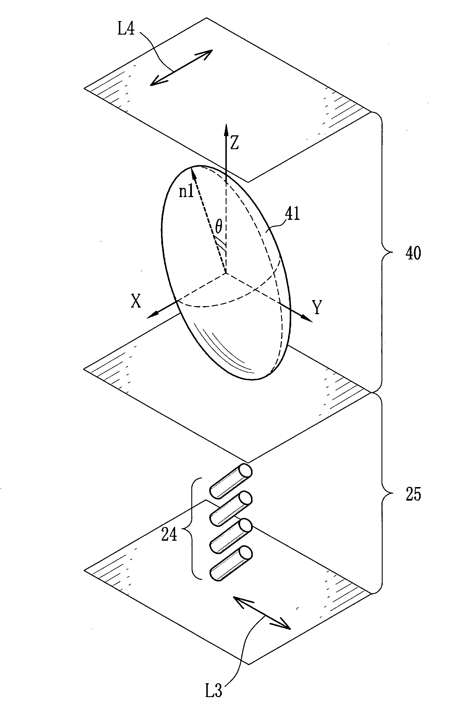
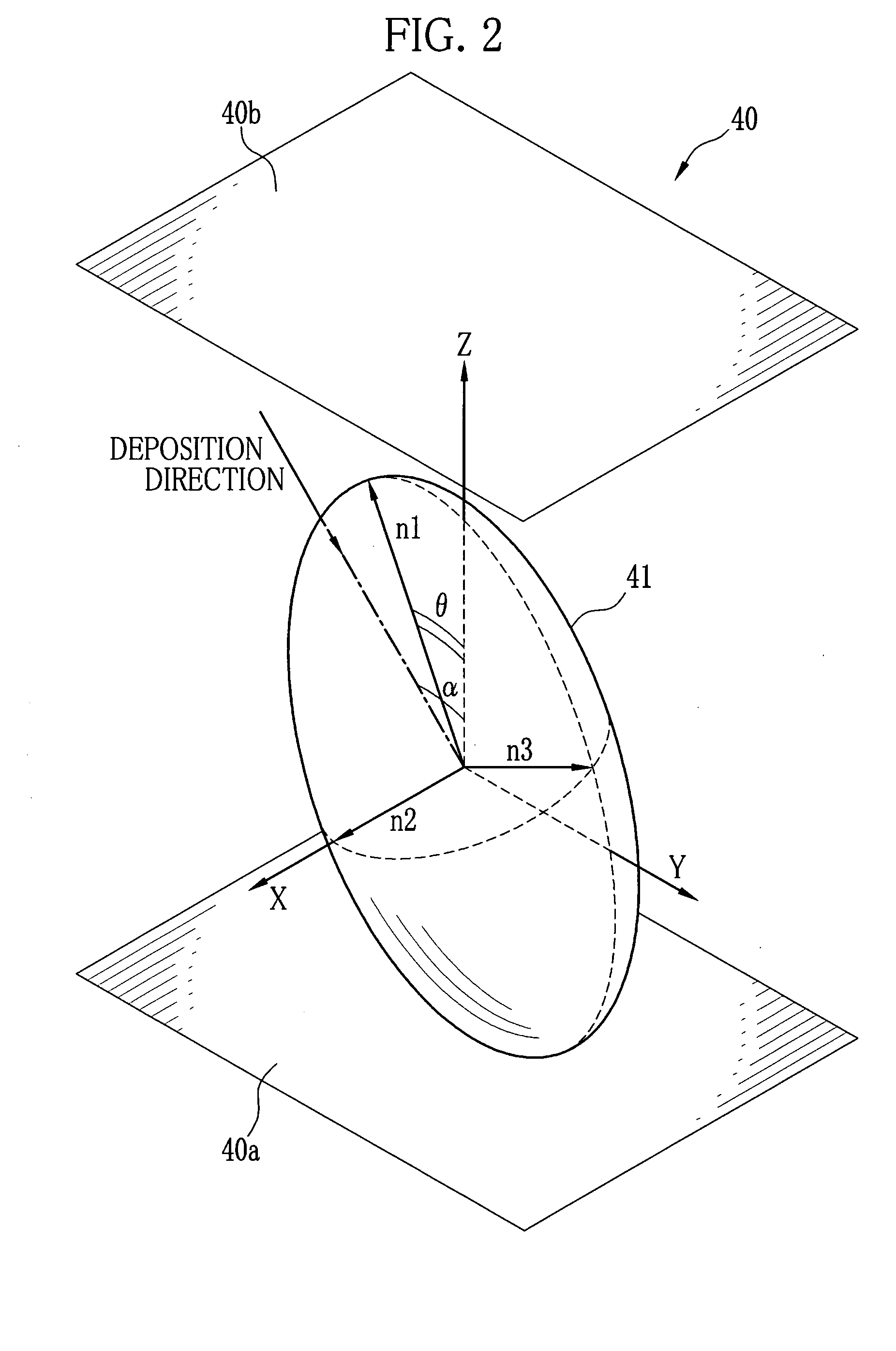
[0070]This phase compensator having a biaxial birefringent component exhibited a frontal retardation of 65 nm to 550 nm light, with principal refractive indices n1 of 1.760, n2 of 1.730 and n3 of 1.640. The value T was 0.75. A tilt angle θ of an index ellipsoid to the s...

example 2

[0071]A phase compensator having a biaxial birefringent component on a base plate was obtained under the same conditions as Example 1, except that a physical film thickness was 2.0 μm. This phase compensator exhibited a frontal retardation of 10 nm to 550 nm light, with principal refractive indices n1 of 1.800, n2 of 1.782 and n3 of 1.743. The value T was 0.68. A tilt angle θ of an index ellipsoid to the surface normal of the base plate was 24°. Similar to Example 1, when viewed from the base plate, a slow axis of the frontal retardation of this phase compensator was perpendicular to an orthogonal projection of an evaporation source's rotation axis onto the base plate. This phase compensator was then combined with a liquid crystal projector having a VAN liquid crystal panel, and contrast of a projection image was improved from 800:1 to 1500:1.

example 3

[0072]Using the rotary evaporator 82, tantalum pentoxide was obliquely deposited onto a glass base plate, at a deposition speed of 0.2 nm per second, so as to form a biaxial birefringent component with a physical film thickness of 1.0 μm. A distance between an evaporation source and a rotary shaft of a base was 400 mm, and the base plate was placed 450 mm distant from the rotary shaft and held at 1000 mm high. The base was rotated at a speed of 10 cycles per minute, and during this rotation a polar angle α of a deposition direction was changing from 72° to 35°, and an azimuth angle β was changing between a ±23° range.

[0073]This phase compensator having a biaxial birefringent component exhibited a frontal retardation of 50 nm to 550 nm light, with principal refractive indices n1 of 1.800, n2 of 1.782 and n3 of 1.744. The value T was 0.68. A tilt angle θ of an index ellipsoid to the surface normal of the base plate was 24°. When viewed from the base plate, a slow axis of the frontal r...


PUM

PropertyMeasurementUnit
cone angleaaaaaaaaaa
tilt angleaaaaaaaaaa

Abstract

A phase compensator having a biaxial birefringent component (40) is fabricated by oblique deposition of an inorganic material on a base plate (69). A polar angle of an evaporation path of the inorganic material is controlled in a predetermined angular range to a surface normal of the base plate (69). In the oblique deposition process, the base plate (69) is oscillated in a horizontal direction. The phase compensator is arranged such that its slow axis (L4) is perpendicular to a slow axis (L3) of tilt components (24a, 24b) in a liquid crystal panel (20), and that an index ellipsoid (41) is tilted in an opposite direction to a tilt direction of the tilt components (24a, 24b).

Description

TECHNICAL FIELD[0001]The present invention relates to a biaxial birefringent component used with liquid crystal panels for compensating optical retardance, a method for manufacturing the same, and liquid crystal projectors.BACKGROUND ART[0002]Liquid crystal projectors are widely used to project images on a screen. The liquid projectors are classified into two types, a front-projection type to project images from the front side of a screen, and a rear-projection type to project images from the rear side of a screen.[0003]Also, liquid crystal panels (liquid crystal cells) are classified into a transmission type and a reflection type, each of which is used in the liquid crystal projector. When projecting an image, the liquid crystal projector firstly generates information light by casting light onto a liquid crystal panel that displays an image, and projects the information light through a projection lens to form an image on a screen. However, the liquid crystal panels, which act on di...

Claims


Application Information

Patent Timeline
Patent Type & Authority Applications(United States)
IPC IPC(8): G02F1/1335G02B5/30G02F1/13
CPCG02B5/3083G02F2413/10G02F2413/12H04N9/3197H04N9/3105H04N9/3167G03B21/14G03B21/006G03B21/2073C23C14/083C23C14/225C23C14/30C23C14/505
Inventor NAKAGAWA, KENICHITAKAHASHI, HIROKIHASHIZUME, TARO
Owner FUJIFILM CORP
Why Eureka
Try Eureka