Chemical reaction-based thermal management system and method

a technology of thermal management system and chemical reaction, applied in the direction of lighting and heating apparatus, domestic cooling apparatus, energy-efficient board measures, etc., can solve the problems of reducing restricting the operational envelope, and affecting the efficiency of thermal management, so as to achieve low cost, high thermal capacity, and low weight cooling

Active Publication Date: 2010-09-23
THE BOEING CO
View PDF8 Cites 12 Cited by
  • Summary
  • Abstract
  • Description
  • Claims
  • Application Information

AI Technical Summary

Benefits of technology

[0008]This need for a chemical reaction-based thermal management system and method is satisfied. Unlike known systems and methods, embodiments of the system and method of the disclosure may provide one or more of the following advantages: provides a chemical reaction-based thermal management system and method that use endothermic chemical reactions to absorb heat from a heat exchanger or heat source and control the conditions for conducting endothermic chemical reactions so as to match the demands of, including without limitation, temperature and rate, of the thermal load being cooled; provides a chemical reaction-based thermal management system and method having near constant temperature, controllable cooling of a heat source by using one of a number of endothermic chemical reactions with high thermal capacity as the heat sink; provides a chemical reaction-based thermal management system and method providing low cost, low weight cooling and improved performance of airborne or weight-limited payloads; provides a chemical reaction-based thermal management system and method having greater payload capabilities within fixed constraints, including without limitation, weight and platform size; provides a chemical reaction-based thermal management system and method that allow heat to be absorbed at a low temperature

Problems solved by technology

The heat generated may be a large amount of heat over a short period of time.
However, such direct heat rejection systems may use large quantities of ram air, which is air outside of the aircraft, and performance may be dependent on ambient temperature, thus restricting the operational envelope.
However, such closed cycle refrigeration systems may be ill-suited to direct management of thermal loads owing to power, weight, and slow transient response.
However, such thermal mass for sensible heat systems may provide limited thermal capacity over a relatively small temperature range d

Method used


Image

  • Chemical reaction-based thermal management system and method
  • Chemical reaction-based thermal management system and method
  • Chemical reaction-based thermal management system and method

Examples


Embodiment Construction

[0022]Disclosed embodiments will now be described more fully hereinafter with reference to the accompanying drawings, in which some, but not all of the disclosed embodiments are shown. Indeed, several different embodiments may be provided and should not be construed as limited to the embodiments set forth herein. Rather, these embodiments are provided so that this disclosure will be thorough and complete and will fully convey the scope of the disclosure to those skilled in the art.

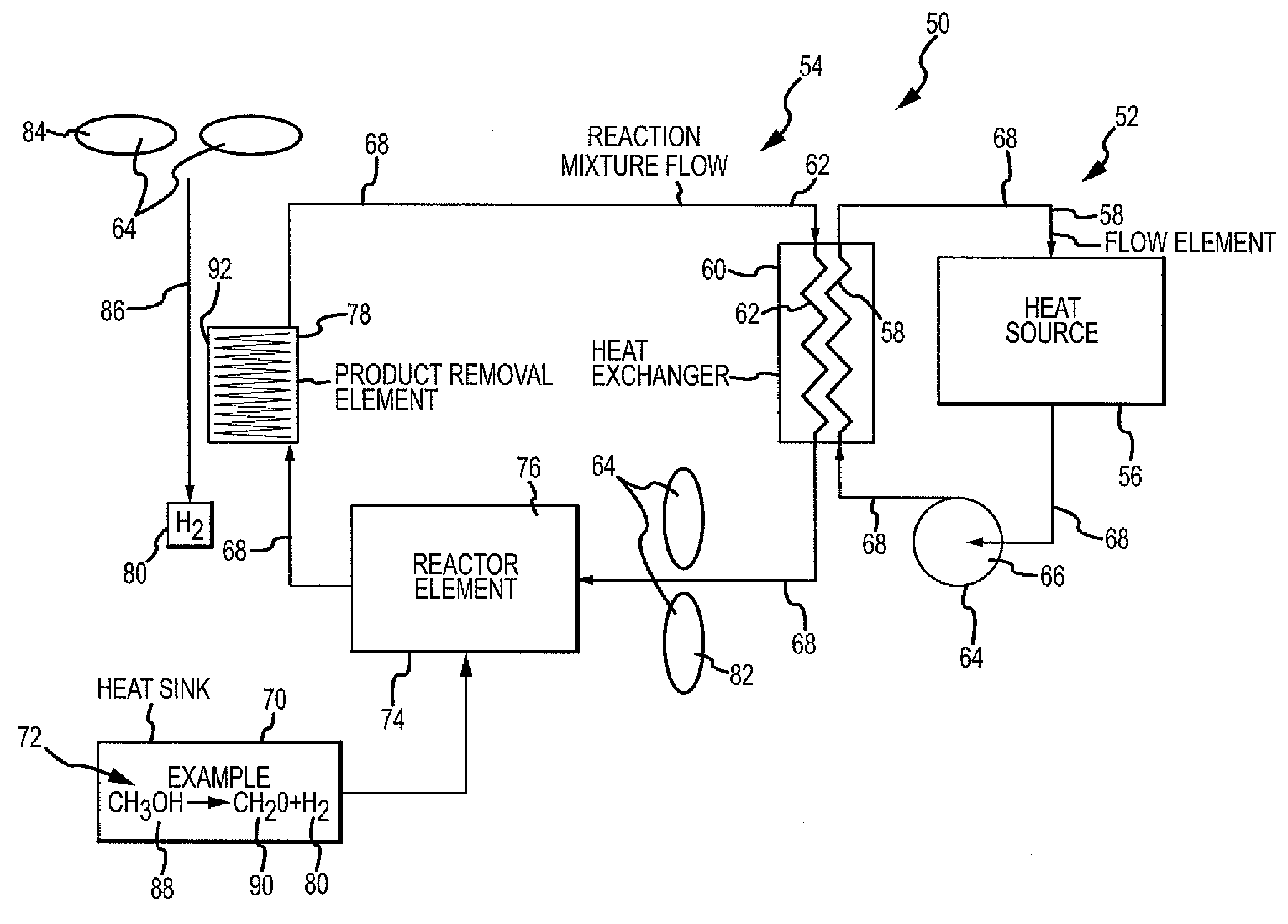
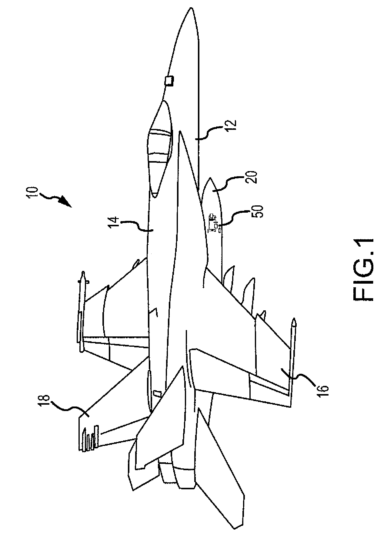
[0023]The disclosure provides for a chemical reaction-based thermal management system and method for using endothermic chemical reactions to absorb heat from a heat exchanger or heat source. The system and method of the disclosed embodiments may be used in aircraft, satellites, or other suitable vehicles and craft. Accordingly, one of ordinary skill in the art will recognize and appreciate that the system and method of the disclosure can be used in any number of applications involving a chemical reaction-b...


PUM


Abstract

The disclosure provides for a chemical reaction-based thermal management system and method. The system comprises a heat source for heating a first flow element, a heat exchanger for transferring heat from the first flow element to a reaction mixture flow, and a heat sink comprising one or more endothermic chemical reactions to absorb heat from the heat exchanger. The system further comprises a reactor element for approaching chemical equilibrium of the reaction mixture flow, a product removal element for removing one or more products from the one or more endothermic chemical reactions, and a plurality of driver elements for moving the first flow element and for moving the reaction mixture flow.

Description

BACKGROUND[0001]1) Field of the Disclosure[0002]The disclosure relates to thermal management systems and methods. In particular, the disclosure relates to chemical reaction-based thermal management systems and methods.[0003]2) Description of Related Art[0004]Various components in aircraft, satellites, and other vehicles and craft may generate heat and require cooling. For example, without limitation, line replaceable units and other components in an aircraft or satellite network may require cooling to maintain those components at an appropriate operating temperature. These types of components may generate heat constantly. Other components may generate heat on a non-constant basis. These types of components may generate heat based on an event that may be periodic or non-periodic. For example, without limitation, directed energy weapons, such as lasers or high power microwave systems, that may be carried as a payload may generate heat when those weapons are used. The heat generated ma...

Claims


Application Information

Patent Timeline
IPC IPC(8): F28D15/00
CPCB64D13/00B64D2013/0614B64D2013/0633Y02T50/56F28D15/00Y02T50/44F25D5/00Y02T50/50Y02T50/40
Inventor ULLMAN, ALAN Z.NEWMAN, CLYDE D.
Owner THE BOEING CO
Why Eureka
Try Eureka