Holder for semiconductor manufacturing equipment
a technology for semiconductor manufacturing equipment and holders, applied in the direction of ohmic-resistance heating details, coatings, chemical vapor deposition coatings, etc., can solve the problems of frequent sparks between poor corrosion resistance of electrode terminals and lead wires for power supplies, and electrical leakag
- Summary
- Abstract
- Description
- Claims
- Application Information
AI Technical Summary
Benefits of technology
Problems solved by technology
Method used
Image

Examples
example 1
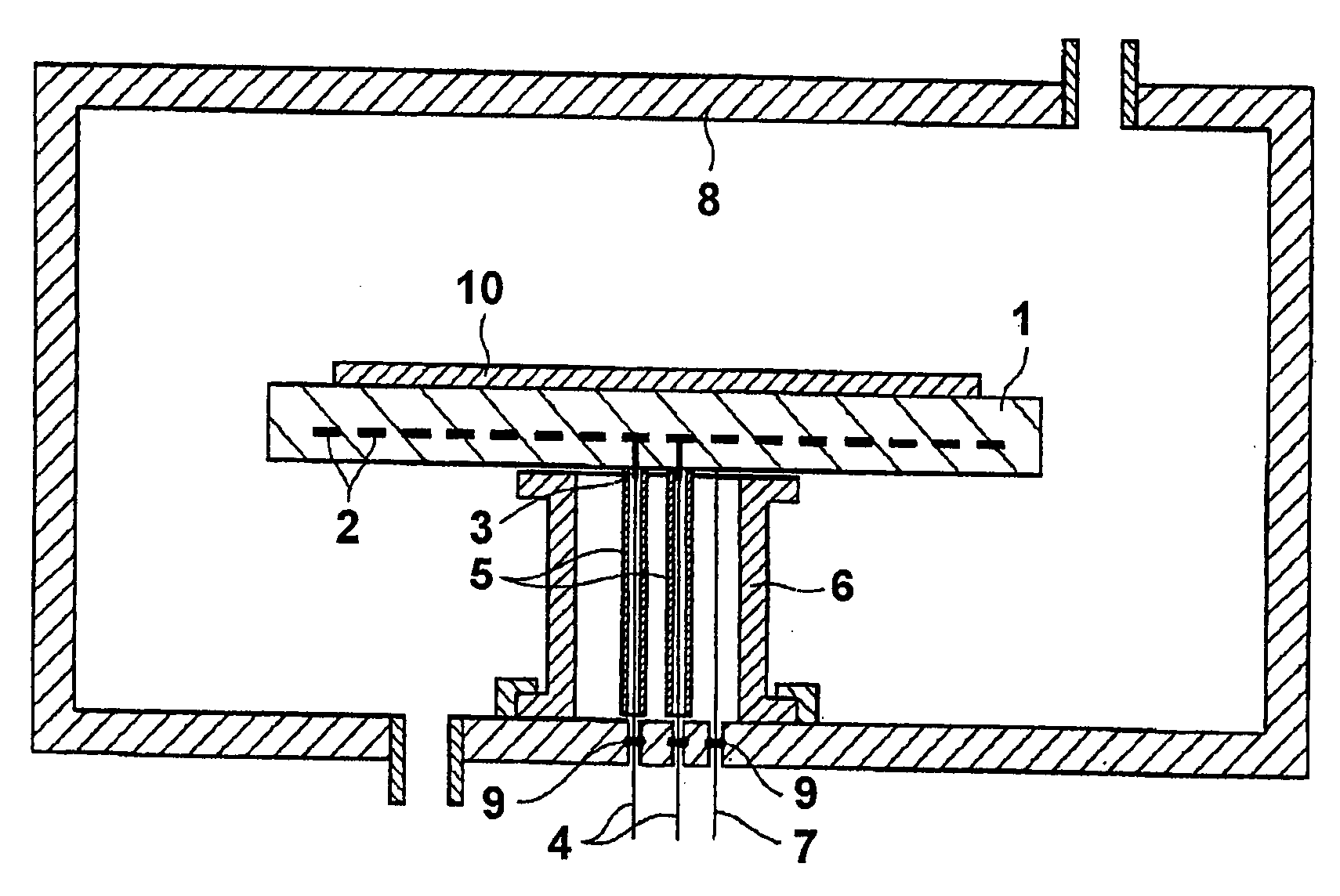
[0046]0.5 weight percent yttria (Y2O3) was added as a sintering agent to aluminum nitride (AlN) powder, and after further adding an organic binder, dispersing and mixing, spray-drying was used for granulation. The granulated powder was molded using a uniaxial press, to obtain, after sintering, two disc-shaped molded bodies of diameter 350 mm and thickness 5 mm. Also, a sintering agent with the same composition was added to the same AlN powder, and after further adding an organic binder for use in extrusion, a dispersing agent and solvent, followed by kneading, the kneaded material was then extrusion-molded to obtain, after sintering, two molded bodies in tube shapes, with external diameter 10 mm, inner diameter 8 mm, and of length 100 mm.
[0047]These two disc-shaped molded bodies and two tube-shaped molded bodies were degreased in a nitrogen flow at a temperature of 900° C., and were then further sintered for five hours at a temperature of 1900° C. in a nitrogen flow. The AlN sintere...
example 2
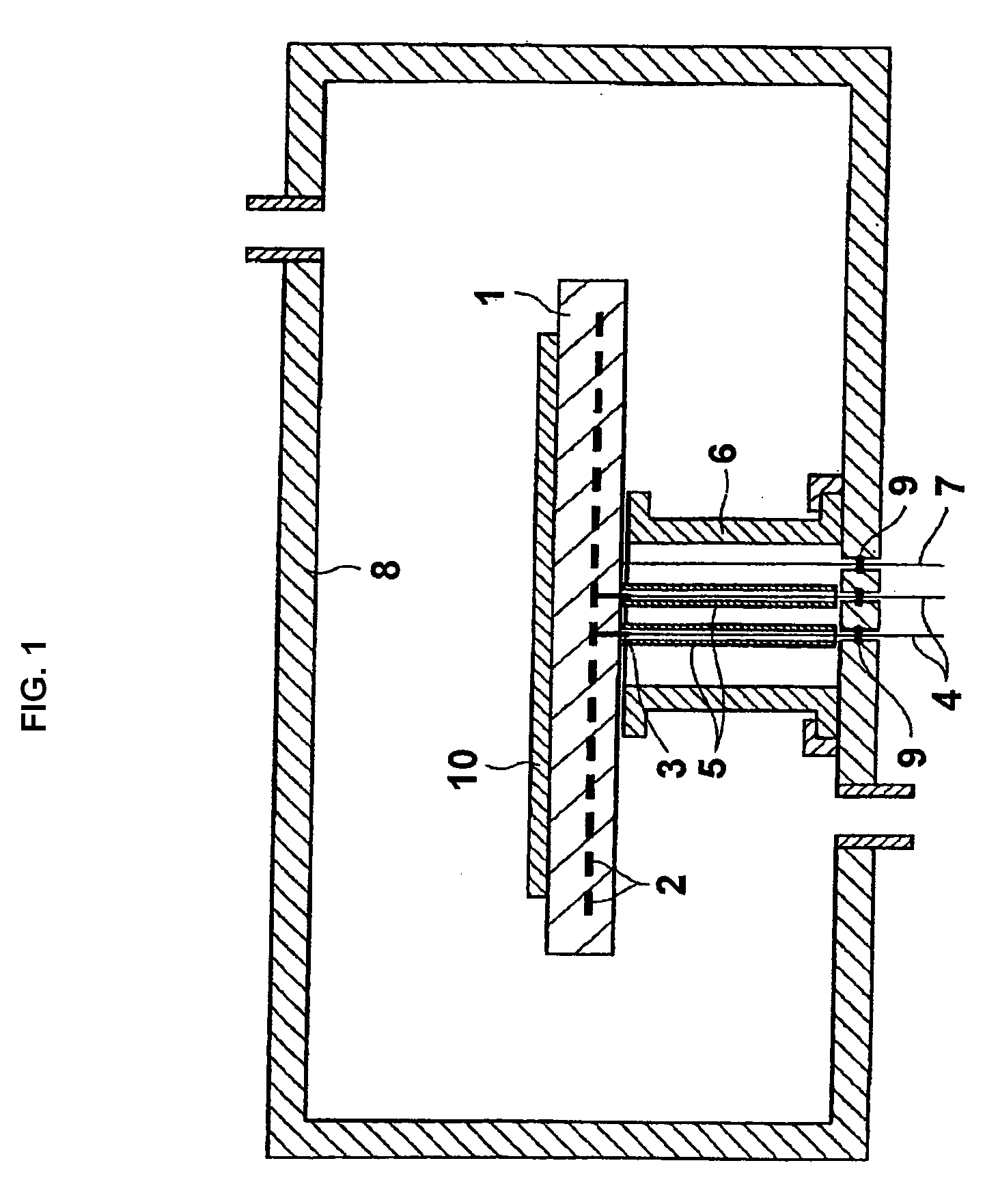
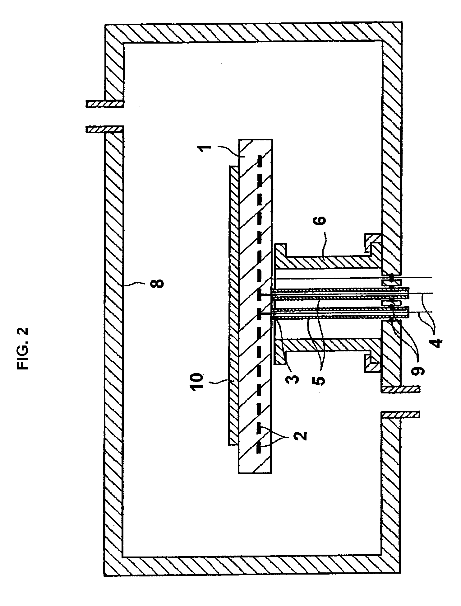
[0054]As shown in FIG. 2, except for extending the other ends of the AlN insulating tubes 5 to pass through the bottom of the chamber 8, and using O-rings 9 to hermetically seal the spaces between the surfaces on the other ends of the insulating tubes 5 and the bottom of the chamber 8, the device was configured the same as Example 1. Evaluations of the equipment configured in this way were performed the same as those of Example 1.
[0055]The ceramic holder was heated to 500° C. under the same conditions as in the Example 1, and no sparking between the electrode terminals 3 and lead wires 4 or other problems occurred even when the power supply was turned on and off 500 times. Moreover, no problems occurred in any of ten ceramic holders 1 subjected to 500 cycles of rising-temperature and falling-temperature processes. The thermal uniformity of the ceramic holder was 500° C.±0.46%.
example 3
[0056]As shown in FIG. 3, except for mating the two AlN insulating tubes 5a, 5b having different diameters for use as the insulating tubes, the device was configured the same as Example 2. The insulating tubes 5a had an outer diameter of 12 mm, inner diameter of 10.5 mm, and length of 60 mm. The insulating tubes 5b had an outer diameter of 10 mm, an inner diameter of 8 mm, and a length of 60 mm.
[0057]The equipment configured in this way was evaluated under the same conditions as in Example 1. That is, the ceramic holder was heated to 500° C., and upon turning the power supply on and off 500 times, no sparking between the electrode terminals and lead wires or other problems occurred. Moreover, no problems occurred in any of ten ceramic holders 1 even when rising-temperature and falling-temperature processes were repeated 500 times. The thermal uniformity of the ceramic holder was 500° C.±0.46%.
PUM
| Property | Measurement | Unit |
|---|---|---|
| Fraction | aaaaa | aaaaa |
| Pressure | aaaaa | aaaaa |
| Temperature | aaaaa | aaaaa |
Abstract
Description
Claims
Application Information
 - R&D
- Intellectual Property
- Life Sciences
- Materials
- Tech Scout
- Unparalleled Data Quality
- Higher Quality Content
- 60% Fewer Hallucinations
Browse by: Latest US Patents, China's latest patents, Technical Efficacy Thesaurus, Application Domain, Technology Topic, Popular Technical Reports.
© 2025 PatSnap. All rights reserved.Legal|Privacy policy|Modern Slavery Act Transparency Statement|Sitemap|About US| Contact US: help@patsnap.com