Decorative part

a technology of decorative parts and coatings, applied in the field of decorative parts, can solve the problems of reducing the appearance quality of the coating, the flaws that cannot be dissolved, and the coating film prepared by any coating is soft, so as to achieve beautiful color tone, high brightness, and the effect of high brightness

Inactive Publication Date: 2010-10-07
CITIZEN WATCH CO LTD
View PDF3 Cites 15 Cited by
  • Summary
  • Abstract
  • Description
  • Claims
  • Application Information

AI Technical Summary

Benefits of technology

[0038]In the present invention, as described above, the hardening layer, which comprises a primary layer comprising a nitride, a carbide or a carbonitride of one or two or more metals selected from Ti, Zr and Hf, the finishing layer comprising Au or an Au alloy and, disposed between the primary layer and the finishing layer, the reflecting layer comprising a metal having a higher reflectance than that of the finishing layer, is formed on the substrate. Since the finishing layer formed on the outermost layer has a very small film thickness and transmits light, the color of the primary layer having low brightness is reflected. Forming the reflecting layer, namely forming the reflecting layer having higher brightness than that of the finishing layer and a high reflectance between the finishing layer and the primary layer having low brightness, the higher brightness in appearance and the more beautiful color tone are realized. Therefore, the improvement in the finishing color tone and the enhancement in the brightness in the gold alloy hard film can be attained more effectively.

Problems solved by technology

The decorative parts obtainable by processing these soft substrates, however, have a problem of great proportions that during the use thereof, the appearance quality is decreased by flaw occurrence etc.
Particularly, Au plating, Au—Ni plating, Au—Pd plating, etc. are carried out widely for decorative parts, but a coating film prepared by any plating is soft and the problem on flaws during the use can not be dissolved.
As the ion plating, a procedure of forming a titanium nitride film can be described but has a problem that the titanium nitride film has inferior adhesion because of having high internal stress and thereby peeling is easily caused.
Any one of the methods cannot solve the film-peeling problems completely.
Furthermore, when peeling is caused, the soft substrate itself is appeared, corrosion occurs on the appeared part with the result that it is impossible to use it as a part.
When only a titanium nitride film is formed, it is difficult to use the film as decorative parts because of having low brightness, inferior sophisticated appearance but having gold colored appearance.

Method used


Image

  • Decorative part
  • Decorative part

Examples


example 1

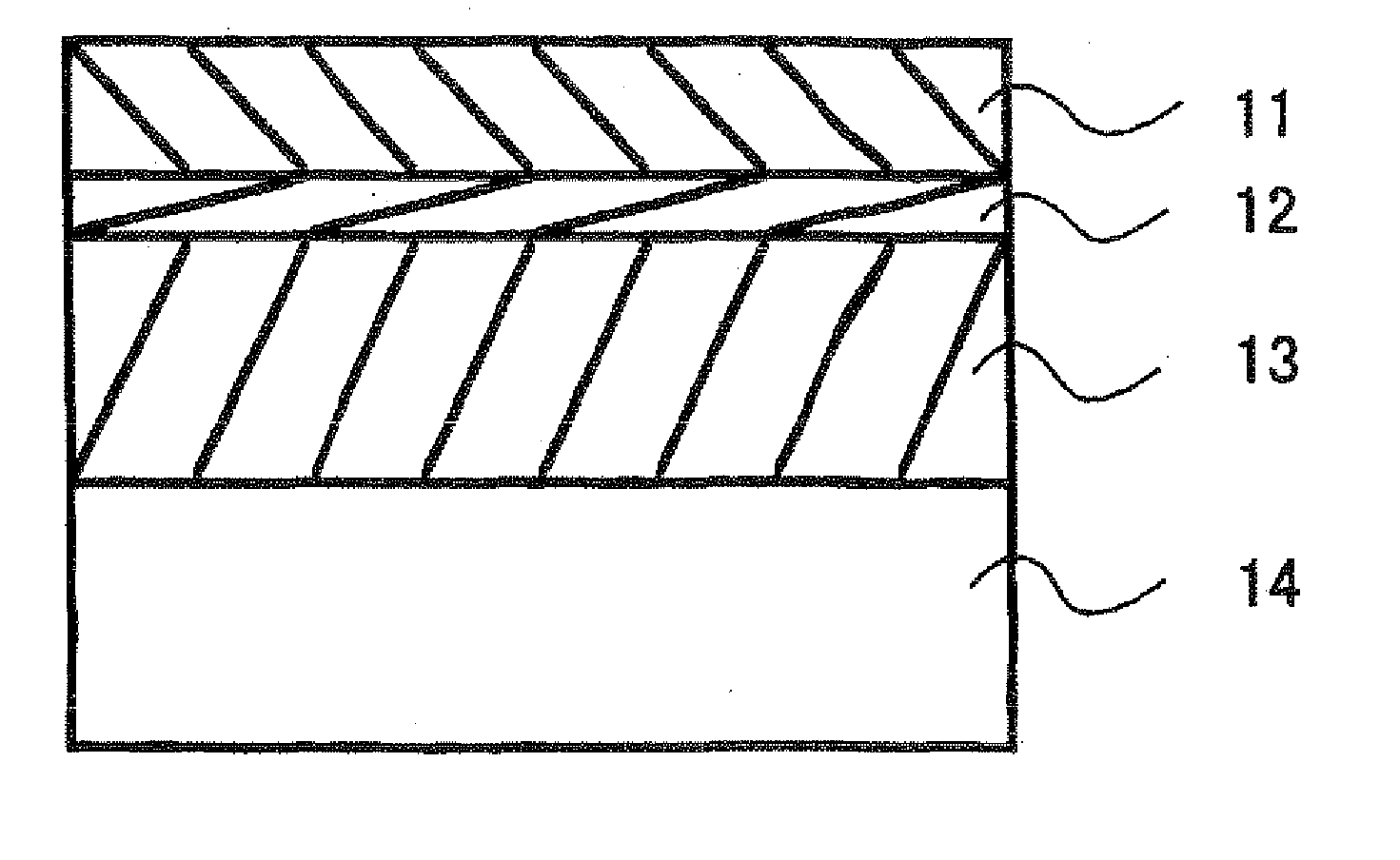
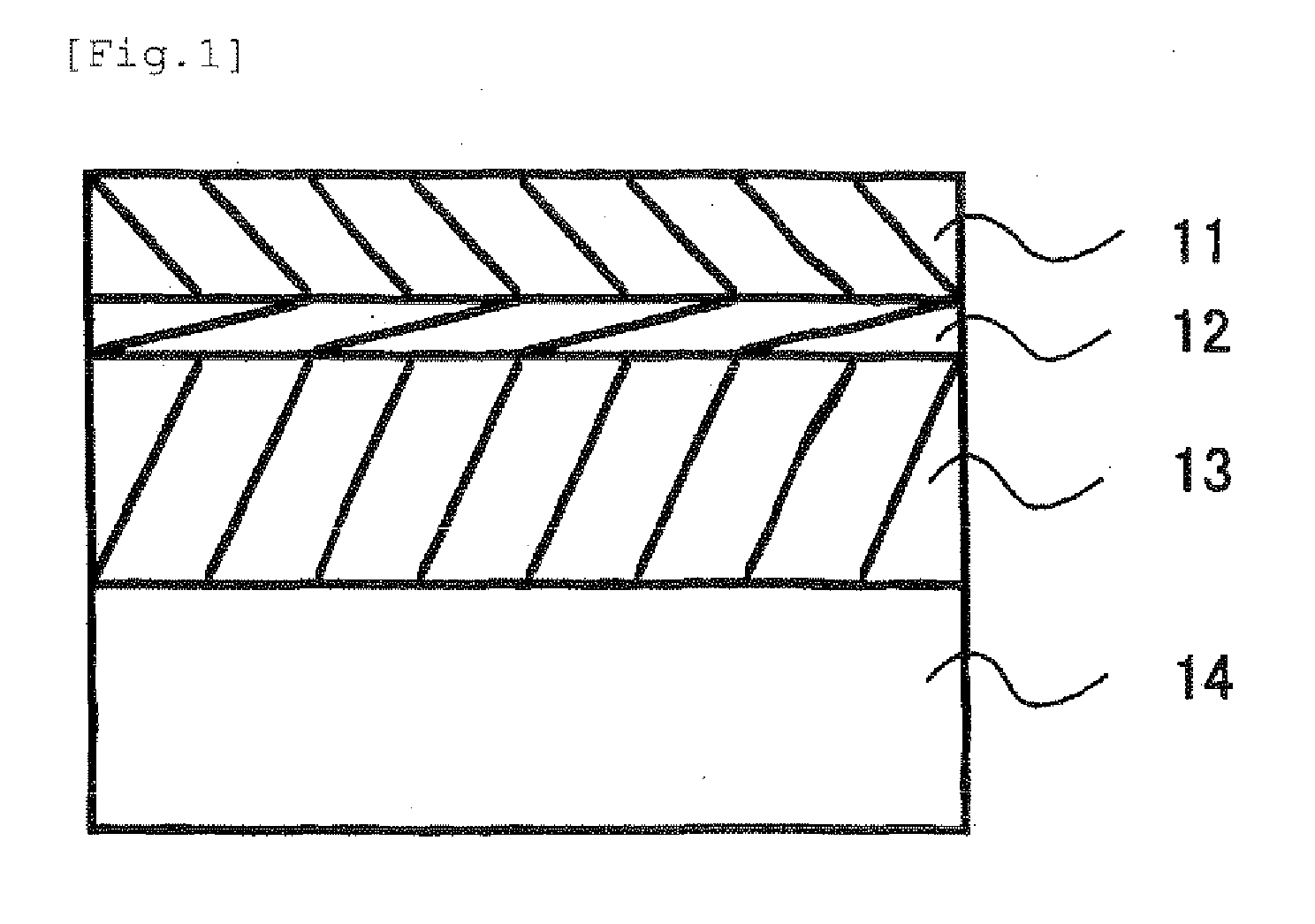
[0081]A substrate 14 was disposed in a vacuum device and the vacuum device was evacuated. Thereafter, a TiN layer was formed as a primary layer 13 on the surface of the substrate 14 using Ti with the DC sputtering method in an atmosphere of a Ar and nitrogen mixed gas plasma generated by introducing Ar and nitrogen with keeping a pressure at 0.2 Pa. Furthermore, a reflecting layer 12 was formed on the primary layer 13 using Pt with the DC sputtering method at the same pressure in an atmosphere of the same gas plasma. Moreover, an Au layer was formed on the reflecting layer 12 using Au with the DC sputtering method at the same pressure in an atmosphere of the same gas plasma to form a finishing layer 11. The film formation was carried out by regulating the film forming times so that the TiN layer constituting the primary layer 13 had a film thickness of 0.8 μm, the finishing layer 11 formed from Au had a film thickness of 0.01 μm (10 nm) and the total film thickness was 0.81 μm (refe...

examples 2 to 24

[0082]In each example, the film formation was carried out in the same manner as described in Example 1 as follows. The vacuum device was evacuated. Thereafter, a HfN, HfCN, TiN, TiCN, ZrN or ZrCN layer was formed as a primary layer 13 on the substrate using Hf, Ti or Zr with the DC sputtering method in an atmosphere of a Ar and nitrogen mixed gas plasma generated by introducing Ar and nitrogen (or an Ar, nitrogen and carbon or hydrocarbon mixed gas plasma generated by introducing Ar, nitrogen and CH4) with keeping a pressure at 0.2 Pa. Furthermore, a reflecting layer 12 was formed on the primary layer 13 using Ru, Pd, Rh, Ag, Os, Ir or Pt with the DC sputtering method at the same pressure in an atmosphere of the same gas plasma. Moreover, an Au or Au alloy layer was formed on the reflecting layer 12 using Au or an Au alloy with the DC sputtering method at the same pressure in an atmosphere of the same gas plasma to form a finishing layer 11. The film formation was carried out by reg...

examples 25 to 47

[0083]In each example, the film formation was carried out in the same manner as described in Example 1 as follows. The vacuum device was evacuated. Thereafter, a HfN, HfCN, TiN, TiCN, ZrN or ZrCN layer was formed as a primary layer 13 on the substrate using Hf, Ti or Zr with the DC sputtering method in an atmosphere of a Ar and nitrogen mixed gas plasma generated by introducing Ar and nitrogen (or an Ar, nitrogen and carbon or hydrocarbon mixed gas plasma generated by introducing Ar, nitrogen and CH4) with keeping a pressure at 0.2 Pa. Furthermore, a reflecting layer 12 was formed on the primary layer 13 using Ru, Pd, Rh, Ag, Os, Ir or Pt with the DC sputtering method at the same pressure in an atmosphere of the same gas plasma. Moreover, an Au or Au alloy layer was formed on the reflecting layer 12 using Au or an Au alloy with the DC sputtering method at the same pressure in an atmosphere of the same gas plasma to form a finishing layer 11. The film formation was carried out by reg...


PUM


Abstract

[Subject] To provide a decorative part having a hardening layer containing Au on the surface, particularly a gold colored decorative part having gloss and color tone inherent in gold, high brightness and high quality.
[Means for Problem the Subject] The decorative part of the present invention comprises a substrate and, superimposed on the substrate, a hardening layer wherein the hardening layer comprises a primary layer comprising a nitride, a carbide or a carbonitride of one or two or more metals selected from Ti, Zr and Hf, a finishing layer comprising Au or an Au alloy having an arbitrary composition such as an Au—Ni alloy, an Au—Cu—Pd alloy etc. and, disposed between the primary layer and the finishing layer, a reflecting layer comprising a metal having a higher reflectance than one constituting the finishing layer, such as Ru, Pd, Rh, Ag, Os, Ir pr Pt.
Thus, the gold colored decorative part having gloss and color tone inherent in gold, high brightness and high quality can be efficiently prepared.

Description

TECHNICAL FIELD[0001]The present invention relates to a decorative part, which comprises a substrate and, superimposed on the surface thereof, a hardening layer, more specifically it relates to a decorative part having a gold colored hardening layer which surface, particularly outermost layer contains gold.TECHNICAL BACKGROUND[0002]To decorative parts such as watch bands, watch cases, bezels, back cases, clasps, buckles, crowns, pierced earrings, earrings, rings, glass frames, pendants, brooches, necklaces, bracelets and the like, soft substrates which are easily processed to parts, for example, a stainless steel, Ti, a Ti alloy and brass have been used widely. The decorative parts obtainable by processing these soft substrates, however, have a problem of great proportions that during the use thereof, the appearance quality is decreased by flaw occurrence etc. This decrease is caused mainly by the low surface hardness of the soft substrates having a Vickers hardness Hv of about 200....

Claims


Application Information

Patent Timeline
Patent Type & Authority Applications(United States)
IPC IPC(8): B32B15/04B32B37/00
CPCA44C27/006C22C5/02Y10T428/12576C23C14/0664Y10T156/1093C23C14/0015
Inventor HAYAKAWA, MAKIMURATA, YASUSHI
Owner CITIZEN WATCH CO LTD
Why Eureka
Try Eureka