Electrode for electrochemical device

a technology of electrochemical devices and electrodes, applied in the field of electrodes, can solve problems such as separation of active materials, and achieve the effects of suppressing the diffusion of components, suppressing the deformation of electrode plates, and suppressing the separation of active materials

Inactive Publication Date: 2010-10-21
PANASONIC CORP
View PDF4 Cites 33 Cited by
  • Summary
  • Abstract
  • Description
  • Claims
  • Application Information

AI Technical Summary

Benefits of technology

[0021]The invention can provide an electrode capable of suppressing the diffusion of the component forming the current collector into the active material layer, increasing the adhesion between the current collector and the active material layer, and suppressing the deformation of the electrode plate and the separation of the active material due to battery charge / discharge reactions.
[0022]Therefore, when the electrode for an electrochemical device according to the invention is used as an electrode for a lithium ion secondary battery, the capacity of the battery can be heightened and the cycle characteristics can be improved.
[0023]Also, when the electrode for an electrochemical device according to the invention is used as an electrode for an electrochemical capacitor, in particular, in place of a conventional graphite electrode, the resultant electrochemical capacitor can provide high energy density not achieved with a conventional electrode such as a graphite electrode.

Problems solved by technology

Since such volume expansion causes a significantly large stress at the interface between the current collector and the active material, it may cause separation of the active material from the current collector.

Method used


Image

  • Electrode for electrochemical device
  • Electrode for electrochemical device
  • Electrode for electrochemical device

Examples


example 1

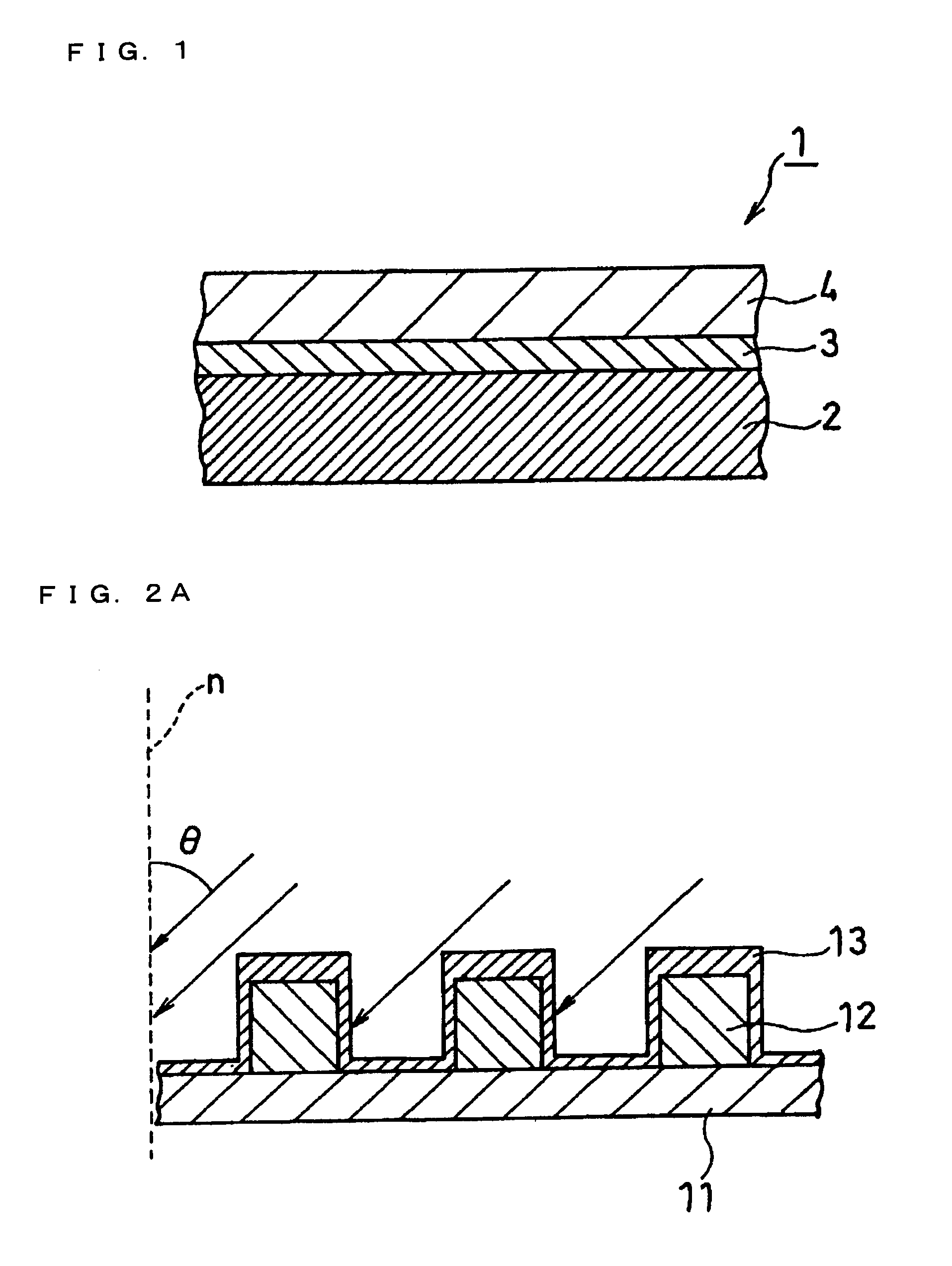
[0098]Referring to FIGS. 2A and 2B, a current collector 11 having regularly arranged protrusions 12 on its surface was produced first. In producing the current collector 11, a negative photoresist was applied onto a rolled copper foil of 18 μm in thickness, and the resist film on the copper foil was exposed to light and developed through a negative mask having rhombus patterns. On the grooves thus formed, copper particles were deposited by electrolysis. Thereafter, the resist was removed, and the protrusions 12 each having a rhombus shape in a plan view were formed. The protrusions 12 were formed such that the protrusion height h1 was 10 μm, the lengths of the long diagonal and the short diagonal of the rhombus portion on the top surface were 28 μm and 12 μm, respectively. The ten-point average height (R2) of the protrusions 12 measured at the top surface was 0.9 μm.

[0099]On the surface of the current collector 11 thus obtained, a thin layer 13 composed of titanium was formed by spu...

example 2

[0107]A copper foil having protrusions 12 formed in the same manner as in Example 1 was used as the current collector 11, and on the surface of the current collector 11, a 0.1-μm-thick thin layer 13 composed of titanium was formed.

[0108]In forming an active material layer, first, an active material was vapor deposited on the surface of the thin layer 13 on the protrusions 12. At this time, the height h1 of the columns was adjusted to 3 μm. Thereafter, the support table 43 was slanted in the opposite direction to a position where the angle of slant θ was −60°, and vapor deposition of active material was performed under the same conditions as in Example 1, to grow columns 14. The height h1 of the columns additionally formed was adjusted to 3 μm. Such processes were repeated alternately to perform vapor deposition seven times in total, whereby columns 14 each having six bents were formed.

[0109]In the negative electrode thus obtained (Sample 4), the height h1 of the columns 14 was 21 μm...


PUM

PropertyMeasurementUnit
first ionization energiesaaaaaaaaaa
thicknessaaaaaaaaaa

Abstract

A problem to be solved by the invention is to provide an electrode for an electrochemical device which has a high capacity, suppresses the separation of an active material due to charge / discharge, and exhibits good cycle characteristics. To solve this problem, in the invention, an electrode 1 for an electrochemical device includes a current collector 2, an active material layer 4 formed over the current collector 2, and a thin layer 3 formed at least a part of the space between the current collector 2 and the active material layer 4. The active material layer 4 includes an active material which does not form a chemical bond with a component forming the current collector 2, and the like, and the thin layer 3 includes a component with a polarizability higher than that of the component forming the current collector 2.

Description

TECHNICAL FIELD[0001]The present invention relates to an electrode used in electrochemical devices such as lithium ion secondary batteries and electrochemical capacitors, and further relates to improvement in adhesion between a current collector of an electrode and an active material layer thereof for electrochemical devices.BACKGROUND ART[0002]In recent years, with developments made in portable devices such as personal computers and cell phones, there is an increasing demand for batteries as their power source. Also, high energy density and excellent cycle characteristics are demanded of batteries for the above-mentioned portable devices.[0003]Therefore, in response to such a demand, high-capacity active materials are being newly developed. Among them, simple substances, oxides, or alloys of silicon (Si) and tin (Sn) are seen as promising as active materials with remarkably high capacities. For example, in a negative electrode for a lithium secondary battery described in PTL 1, a s...

Claims


Application Information

Patent Timeline
Patent Type & Authority Applications(United States)
IPC IPC(8): H01M4/02H01G9/022H01M4/58H01M4/00H01G11/22H01G11/30H01G11/66H01G11/68H01G11/70H01M4/13H01M4/134H01M4/136H01M4/48H01M4/66H01M4/70
CPCH01G9/016H01G9/058H01G11/06H01G11/28H01G11/68H01G11/70Y02E60/13H01M4/58H01M4/66H01M4/667H01M10/0525Y02E60/122H01M4/485H01G11/22H01G11/74Y02E60/10
Inventor YAMAMOTO, TAISUKEIWAMOTO, KAZUYAKOGETSU, YASUTAKA
Owner PANASONIC CORP
Why Eureka
Try Eureka