Method for a continuous rapid thermal cycle system

a rapid thermal cycle and thermal cycle technology, applied in the direction of fluid controllers, biochemical equipment and processes, fermentation, etc., can solve the problems of inability to easily and quickly adapt to the device, the device is not designed to produce mass quantities of dna, and the time-consuming and laborious processes of the process, so as to improve the specificity and yield of the reaction, minimize thermal transfer, and achieve efficient and maintained

Active Publication Date: 2010-10-21
APPLIED DNA SCI
View PDF14 Cites 9 Cited by
  • Summary
  • Abstract
  • Description
  • Claims
  • Application Information

AI Technical Summary

Benefits of technology

[0040]Temperatures for the 3 steps of PCR when carried out according to the present invention are about 95° C., 57° C. and 72° C., respectively. However, the temperatures can be varied to increase specificity and yield of the reaction.
[0041]The present invention is directed to a method and composition for simultaneously maintaining multiple temperature regions within a single physical structure. The present invention is therefore particularly suited for use in the automated thermal cycling of substances, such as those used in the amplification of nucleic acid sequences. With reference to the drawings, and in particular to FIGS. 1-13, a thermal cycle system 100 of the present invention preferably comprises a temperature control body 102 having at least two sectors 118 and a path 104 that cyclically passes from one initial sector 118 to each successive sector 118 in turn, thereafter returning to the initial sector 118 and cyclically repeating passes from one sector 118 to the next sector 118 as many times as is desired. The path 104 traverses the sectors 118 by passing along an exterior surface 132 of the temperature control body 102 from one sector 118 to each successive sector 118, by boring through the sectors 118 internally from one sector 118 to each successive sector 118, or by a combination of such external or internal travel.
[0042]Each sector 118 comprises at least one means for changing or obtaining a temperature 120. The means for changing temperature 120 is capable of achieving and maintaining a specific desired temperature. The means for changing temperature 120 is therefore preferably a heater, cooler, Peltier device, heat pump, oven, firebox, thermal reaction chamber, or similar means. Each sector 118 is preferably substantially made of aluminum, aluminum alloy, metal, metal alloy, a thermal conductor, an asymmetric thermal conductor, or combination thereof. The means for changing temperature 120 thereby heats, cools or maintains the temperature of the sector 118 such that the section of the path 104 located in or on each sector 118 is similarly heated, cooled, or maintained at the particular temperature of that sector 118.
[0043]Each sector 118 is also preferably separated from other sectors 118 by a thermal barrier 122 located between the sectors 118. The thermal barrier 122 may be passive, and may comprise a thermal insulator, air, gas, liquid, solid, and / or a combination thereof. The thermal barrier 122 may alternatively or additionally be an active devise or material, such as a Peltier device, which can maintain a significant temperature differential. Each sector 118 therefore acts as an independent temperature sink wherein the means for changing temperature 120 for that sector 118 achieves and maintains a desired temperature throughout that sector 118, and a thermal barrier 122 thermally isolates each sector 118 from the other sectors 118. Multiple temperature regions are thereby efficiently achieved and maintained in a single body. An insulating layer 124 may optionally substantially surround the temperature control body 102 to minimize thermal transfer between the sectors 118 and the surrounding environment.
[0044]The temperature control body 102 may have any desirable shape, such as a cylinder, cone, triangle, rectangle, pyramid, polygon, block, or cube. The sectors 118 may also have any desired shape conforming to sections, parts, or pieces of the temperature control body 102. For example, the sectors 118 may be wedge shaped, arc shaped, or pie-sliced shaped, or may have the shape of sliced portions of a cylinder, cone, triangle, rectangle, pyramid, polygon, block, or cube. The sectors 118 may also be layered, one atop another. There may be any number of desired sectors 118. All the sectors 118 may be the same size, or one or more of the sectors 118 may be different size.
[0045]The thermal cycle system 100 also preferably comprises a plurality of temperature sensors 130. Each sector 118 preferably has one or more temperature sensors 130 located within or adjacent to that sector 118 to measure the temperature within that sector 118 or portion of sector 118. Each temperature sensor 130 produces temperature values output that directly or indirectly represents the temperature of that sector 118. Such temperature sensors 130 may be any conventional instrument for determining temperature. Such temperature sensors 130 may optionally be placed in or on the insulating layer 124.

Problems solved by technology

The process is time intensive, labor intensive, and inefficient, as the tubes must be individually filled with reactants, closed, processed through the automatic cycler, opened, and finally drained of the reaction product that contains the desired amplified DNA.
This device is not designed to produce mass quantities of DNA.
Moreover, the Corbett et al. device is not designed to be easily and quickly adaptable to different PCR reaction requirements.
Modifying the device for different reaction conditions therefore requires re-wrapping the tubing around one or more of the cylinders a different number of times, unwrapping the tubing around one or more of the cylinders to replace one or more of the cylinders with different cylinders, re-routing the tubing around the cylinders in different orders, or another such labor-intensive procedure.
Additionally, efficiency and fine temperature control is reduced as the reaction mixture pockets pass from one cylinder to the next and thermal energy is unintentionally lost or gained at such “gaps.”
This device is not designed for easy modification for providing a number of different reaction conditions, as additional water baths would have to be prepared and added for such modification.

Method used


Image

  • Method for a continuous rapid thermal cycle system
  • Method for a continuous rapid thermal cycle system
  • Method for a continuous rapid thermal cycle system

Examples


example 2

[0069]A reaction mixture with Pluronic is constructed by mixing 3% weight / volume Pluronic F127 with water and adding this to the PCR reaction mix, resulting in the following concentrations:

% ofConcentration ofFinalReagentStock SolutionSolutionMilliQ Water79.9%Pluronic F127Add 3% powder to   3%solutionwater to dissolve,slightly increasingvolumePCR Buffer (matched 10X  10%to enzyme bymanufacturer)pGEM 3ZF+ plasmid  5 milligram / 0.06%milliliterMgCl2150 milliMolar   2%Primer forward 20 microMolar   2%CGATTTCGGCCTATTGGTTAPrimer Reverse 20 microMolar   2%CGGTGAAAACCTCTGACACATaq DNA polymerase  5 units / microliter 0.6%Deoxynucleotide Mix 10 micromole each   2%nucleotide 100%

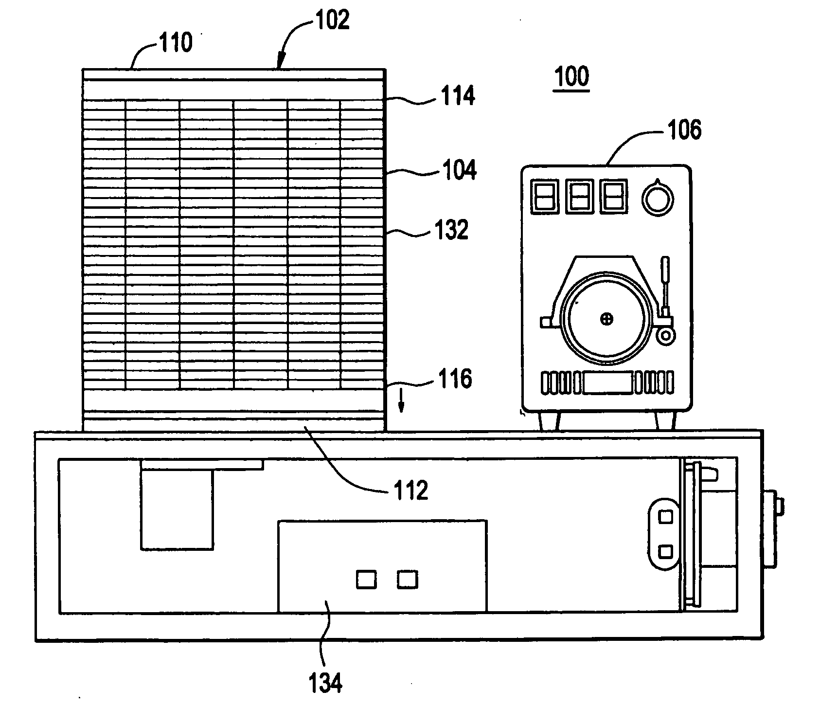
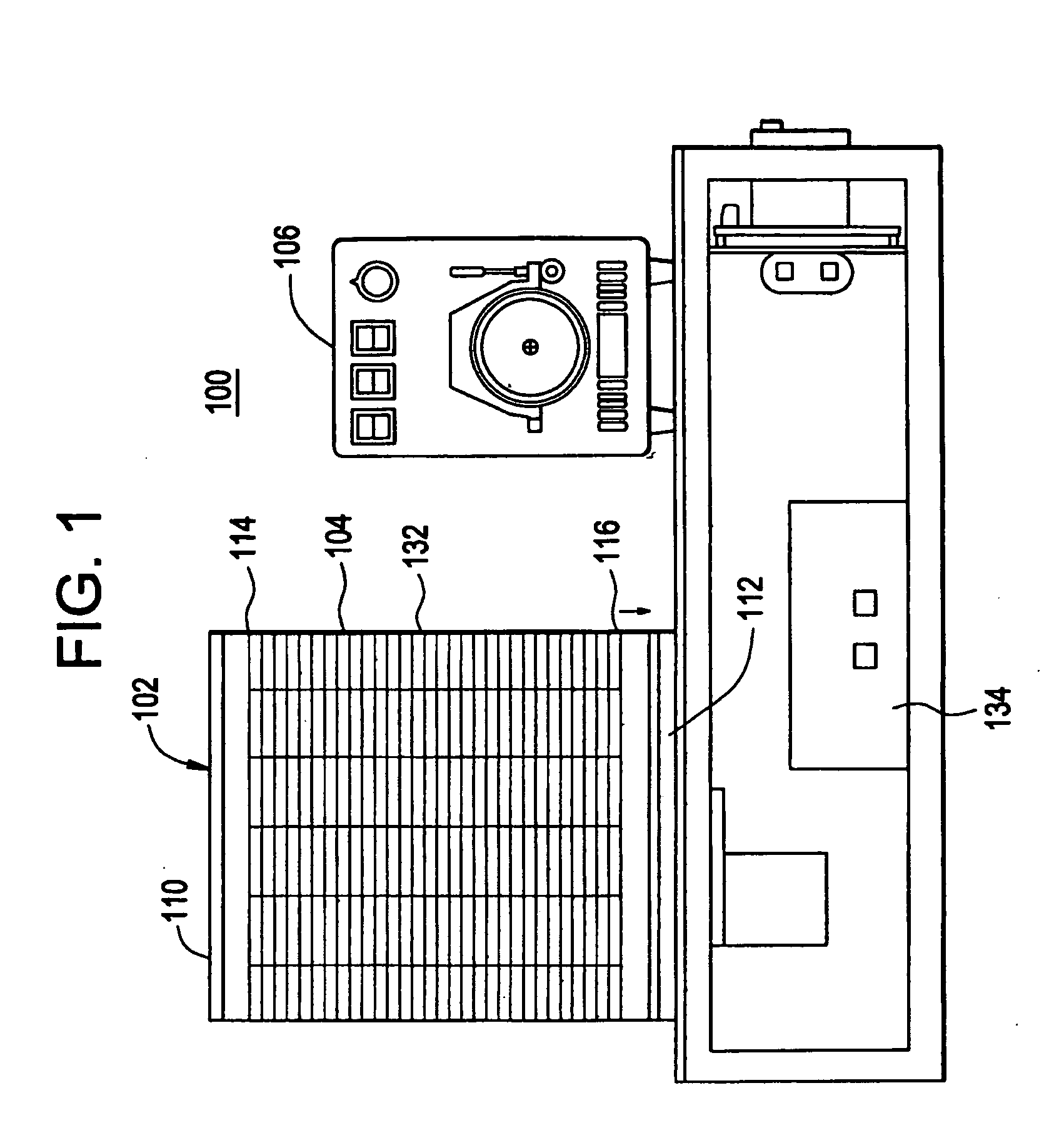
[0070]The PCR mixture is kept chilled before it is pumped through the machine and after collection. The machine uses thirty wraps of PFTE tubing with 1 / 16 inch ID and ⅛ inch OD. The PCR mix is made in volumes up to 500 ml and kept at 4 degrees Centigrade prior to cycling. The sectors of the machine are evenly divided into...

example 3

[0071]A range of Pluronic concentrations are described using the same DNA template, oligonucleotide primers and temperature / flow concentrations as in Example 2 with a reaction mixture with Pluronic F108 that is constructed by mixing 1.5% weight / volume Pluronic F108 with water and adding this to the PCR reaction mixture with the amount of MilliQ water varying to bring the final volume to 100%.

% ofConcentration ofFinalReagentStock SolutionSolutionMilliQ Water  64%-0%Pluronic F108Add 1.5% powder to   8%-72%water to dissolvePCR Buffer (matched 10X   8%to enzyme bymanufacturer)pGEM 3ZF+ plasmid0.1 milligram /    8%milliliterMgCl2 25 milliMolar  12%Primer forward 10 microMolar   4%CGATTTCGGCCTATTGGTTAPrimer Reverse 10 microMolar   4%CGGTGAAAACCTCTGACACATaq DNA polymerase  5 units / microliter0.33%Deoxynucleotide Mix 10 micromole each   2%nucleotide 100%

[0072]The PCR mixture is kept chilled before it is pumped through the machine and after collection. The machine uses thirty wraps of PFTE tubi...

example 4

[0073]This example describes use of 1 rinse of the tubing in the machine with 1.5% Pluronic solution for times ranging from 30 minutes to 60 minutes to pretreat the tubing followed by pumping the PCR reagent mixture which does not contain Pluronic or other surface absorbing polymer. This example used the same DNA template, oligonucleotide primers and temperature / flow concentrations in Example 2 under a reaction mix.

% ofConcentration ofFinalReagentStock SolutionSolutionMilliQ Water  62%-0%PCR Buffer (matched 10X   8%to enzyme bymanufacturer)pGEM 3ZF+ plasmid0.1 milligram /    8%milliliterMgCl2 25 milliMolar  12%Primer forward 10 microMolar   4%CGATTTCGGCCTATTGGTTAPrimer Reverse 10 microMolar   4%CGGTGAAAACCTCTGACACATaq DNA polymerase  5 units / microliter0.33%Deoxynucleotide Mix 10 micromole each   2%nucleotide 100%

[0074]The PCR mixture is kept chilled before it is pumped through the machine and after collection. The machine uses thirty wraps of PFTE tubing with 1 / 32 inch ID and 1 / 16 inc...


PUM

PropertyMeasurementUnit
temperatureaaaaaaaaaa

Abstract

Disclosed herein is an efficient, high speed production scale synthesis method for high molecular weight organic substances, such as DNA. The invention includes a method of conducting a polymerase chain reaction which comprises transporting a liquid through polymeric tubing disposed through a first reaction cycle region and at least a second reaction cycle region, each of which regions comprises at least a first and a second temperature zone, the temperature in each zone of said at least second region being substantially identical to the corresponding first and second zones in said first region, wherein said liquid is an aqueous solution comprising polymerase chain reaction reactants and a surface absorbing polymer.

Description

RELATED APPLICATION[0001]This application claims priority on U.S. Provisional Patent Application No. 60 / 850,103 filed Oct. 6, 2006, entitled “Use of Pluronic F-127 block copolymer surfactant, Pluronic F-68, and Pluronic F-108NF in a non-static DNA amplification solution”. The contents of each of which are incorporated by reference herein in their entirety.INTRODUCTION [0002]Polymerase chain reaction (PCR) is a three step process normally designed for diagnostic, identification or forensic purposes. In the first step, DNA, or a similar molecule, is denatured, also referred to as split, separated or unwound at a temperature of about 94-96° Centigrade (C). In the second step the strands produced in the first step are annealed, also known as primed or hybridized with the polymerase initiator or primer reactant at a temperature of about 55-60° C. In the third step, the thus-primed single strand of DNA is allowed to synthesize a replicate DNA via extension of the primer as individual nucl...

Claims


Application Information

Patent Timeline
Patent Type & Authority Applications(United States)
IPC IPC(8): C12P19/34
CPCB01L7/525B01L2300/0832C12Q1/686B01L2400/0487B01L2300/123
Inventor MURRAY, ELIZABETHGREGG, DEREK ALLENNORTON, MICHAEL LOUISSWICK, JUSTIN THOMASTOWLER, WILLIAM IAN
Owner APPLIED DNA SCI
Why Eureka
Try Eureka