Filter medium and method of manufacturing the same and filter unit

Active Publication Date: 2010-10-28
NITTO DENKO CORP
View PDF18 Cites 27 Cited by
  • Summary
  • Abstract
  • Description
  • Claims
  • Application Information

AI Technical Summary

Benefits of technology

[0047]The filter medium of the present invention may be pleated if necessary, and the shape and size of the pleats are not particularly limited. As an example, the height of the pleats is about 10 to 30 mm.
[0048]The pleated filter medium can be formed by pleating a flat-shaped filter medium by a known pleating machine (such as a rotary pleating machine, a reciprocating pleating machine, or a striping machine). From the viewpoint of reducing the damage to the porous PTFE membrane 2 during the pleating process as much as possible, a reciprocating pleating machine is used preferably.
[0049]In the filter medium of the present invention, the porous PTFE membrane 2, the substrate 11, or the fiber layer 12 may be colored. Each of these layers can be colored by a known method, for example, by kneading a pigment into the material of the layer.
[0050]The filter medium of the present invention can be formed, for example, by a manufacturing method of the present invention described below.
[0051]FIGS. 4 and 5 show an example of the manufacturing method of the present invention.
[0052]First, as shown in FIG. 4, a fiber group 21 containing polyolefin-containing fibers is deposit

Problems solved by technology

PTFE, however, has poor adhesion to polyester, particularly PET.
This type of lamination may cause clogging of the nonwoven fabric due to such high heat, which results easily in a significant decrease in the gas-permeability of the filter medium.
Generally, PTFE has poor adhesion not only to PET but also to materials other than PET.
Therefore, the same problems occur even when a gas-permeable supporting member made of a material other than a PET nonwoven fabric is used.
However, the bonding strength between the PET

Method used


Image

  • Filter medium and method of manufacturing the same and filter unit
  • Filter medium and method of manufacturing the same and filter unit
  • Filter medium and method of manufacturing the same and filter unit

Examples


example 1

Preparation of Porous PTFE Membrane

[0075]First, 100 parts by weight of PTFE fine powder (“Polyflon F-104” (trade name) manufactured by Daikin Industries, Ltd.) was mixed uniformly with 25 parts by weight of hydrocarbon oil, as a liquid lubricant, (“Isopar M” (trade name) manufactured by Esso Oil Co., Ltd.). Next, the resulting mixture was pre-molded under a pressure of 20 kg / cm2, and then the pre-molded article was molded into a rod by extrusion. This rod thus obtained by extrusion molding further was rolled through a pair of metal rolls to obtain a strip-shaped PTFE sheet of 0.2 mm in thickness and 150 mm in width.

[0076]Next, the sheet thus obtained was heated at 220° C. to remove the liquid lubricant contained in the sheet. Then, this unsintered PTFE sheet was stretched in the MD direction (machine direction) by a factor of 20, and then stretched in the TD direction (transverse direction) by a factor of 30. The resulting sheet further was sintered at a temperature of the melting p...

example 2

[0089]A filter medium was obtained in the same manner as in Example 1 except that as a substrate of a gas-permeable supporting member, a PET nonwoven fabric that had been dipped in a fluorine water repellent agent (UNIDYNE, manufactured by Daikin Industries, Ltd.) to be imparted with water repellency was used (the same PET nonwoven fabric as that used in Example 1 except that it was a water repellent-treated fabric).

[0090]The bonding strength between the fiber layer and the substrate in the obtained filter medium was evaluated in the same manner as in Example 1. As a result, the bonding strength between them in the MD direction of the porous PTFE membrane was 2.75 N / 25 mm, and the bonding strength in the TD direction thereof was 2.88 N / 25 mm.

example 3

[0098]A gas-permeable supporting member, in which a fiber layer composed of PE / PET fibers was placed on a substrate made of a PET nonwoven fabric, was obtained in the same manner as in Example 1 except that the weight per unit area of the PET nonwoven fabric was 20 g / m2. The fiber layer was formed to have a weight per unit area of 20 g / m2.

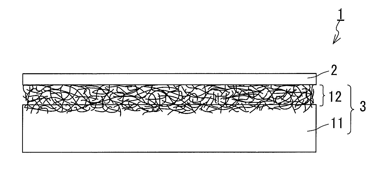
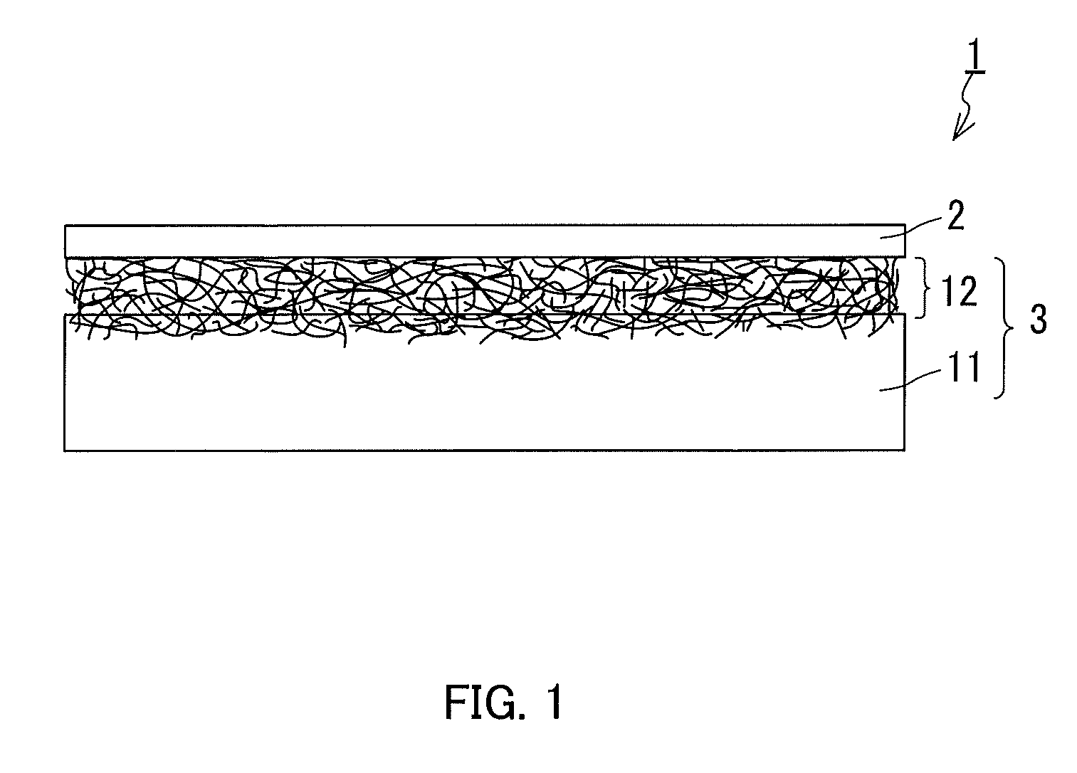
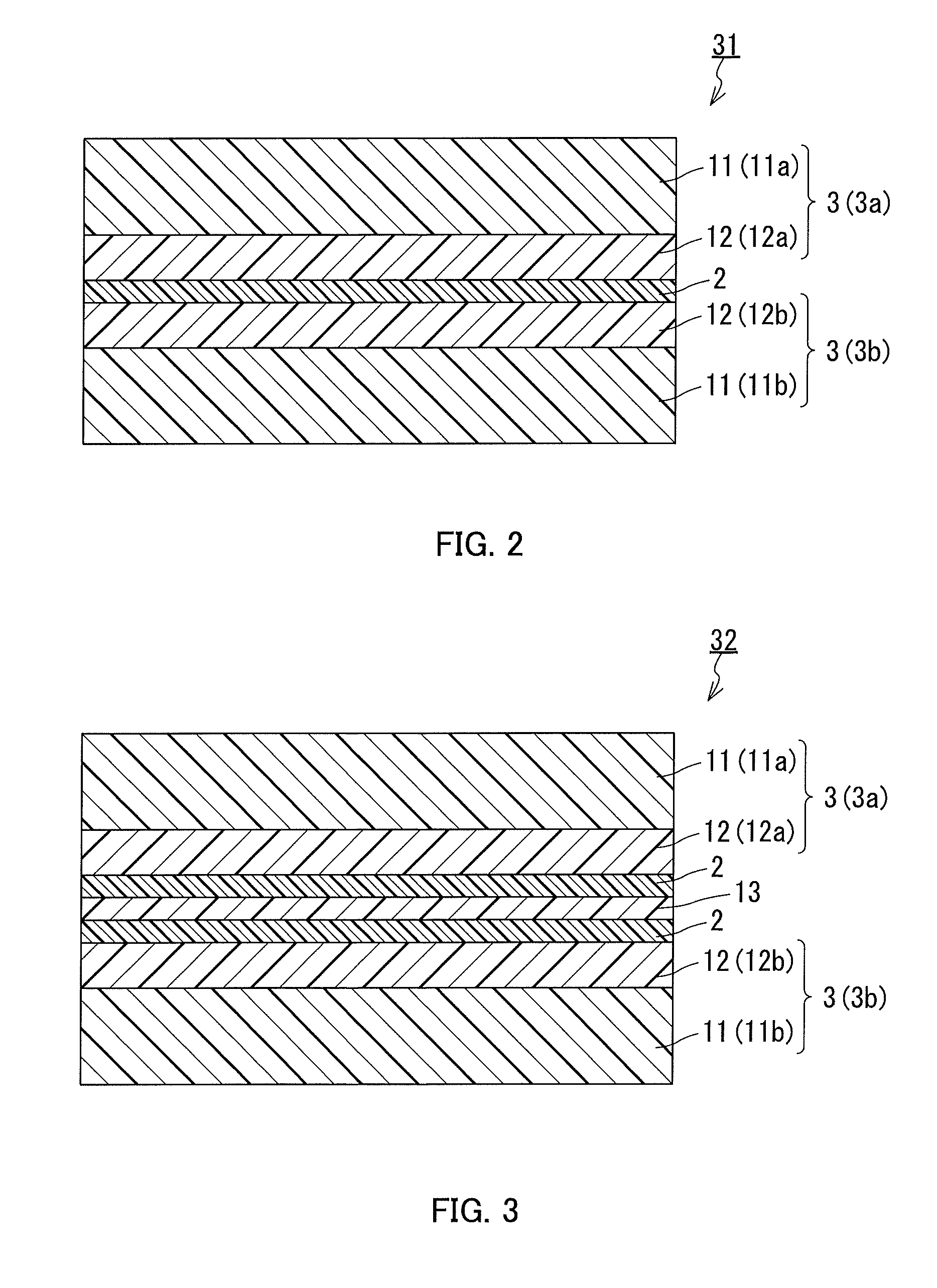
[0099]Next, a pair of the gas-permeable supporting members thus obtained and the porous PTFE membrane prepared in Example 1 were stacked so that the porous PTFE membrane was sandwiched between the gas-permeable supporting members, and then the resulting stacked body was subjected to heat lamination in the same manner as in Example 1. Thus, a filter medium having the structure shown in FIG. 2 was obtained. The porous PTFE membrane and the pair of gas-permeable supporting members were stacked so that the fiber layer of each of the gas-permeable supporting members and the porous PTFE membrane were in contact with each other.

[0100]The collection effici...


PUM

PropertyMeasurementUnit
Fractionaaaaaaaaaa
Lengthaaaaaaaaaa
Speedaaaaaaaaaa

Abstract

Provided is a filter medium including a porous polytetrafluoroethylene (PTFE) membrane and a gas-permeable supporting member that are integrated to ensure sufficient stiffness, having excellent gas permeability, and providing excellent bonding between respective layers included in the filter medium. The gas-permeable supporting member includes: a substrate having gas-permeability; and a fiber layer that is placed on the substrate so as to be in contact with the porous PTFE membrane. The gas-permeable supporting member has a structure in which fibers of the fiber layer enter into the substrate and are entangled with the substrate so that the fiber layer is bonded to the substrate. The fiber layer contains polyolefin-containing fibers that are bonded to the porous membrane.

Description

TECHNICAL FIELD[0001]The present invention relates to a filter medium including a porous polytetrafluoroethylene (PTFE) membrane and a method of manufacturing the same, and to a filter unit.BACKGROUND ART[0002]Filters for high performance cyclone vacuum cleaners, etc. are required to have high collection efficiency. Generally, for such filters, filter media including porous PTFE membranes, filter media obtained by adding binders to glass fibers and forming the mixtures into paper sheets (glass filter media), and filter media obtained by converting meltblown nonwoven fabrics into electret materials (electret filter media) are used. Filter media including porous PTFE membranes, among them, rarely suffer from problems such as the production of fibrils and self-dusting and have a smaller increase in the pressure drop during the use thereof. Because of these advantages, these filter media are expected to be used increasingly.[0003]In a filter through which a large amount of air passes, s...

Claims


Application Information

Patent Timeline
IPC IPC(8): B01D39/20B32B37/04B01D39/16B01D69/10B01D71/26B01D71/36B01D71/48B32B5/24B32B27/30B32B27/32
CPCB01D2239/0654B01D39/1692B01D69/12B01D71/36
Inventor MORI, MASAAKISUZUKI, MASATOSHI
Owner NITTO DENKO CORP
Why Eureka
Try Eureka