Sludge concentration and dehydration method

a technology of sludge concentration and dehydration method, which is applied in water/sewage treatment by ion exchange, separation processes, filtration separation, etc., can solve the problems of long concentration time, difficult to be received by landfills, and the water content of dehydrating sludge cannot be lowered to the optimal level, so as to reduce the size and mass of sludge, reduce the water content, and reduce the size of sludg

Inactive Publication Date: 2010-11-11
SWISON CREATIVE ENVIRONMENTAL SOLUTIONS CO LTD
View PDF16 Cites 16 Cited by
  • Summary
  • Abstract
  • Description
  • Claims
  • Application Information

AI Technical Summary

Benefits of technology

[0018]The present invention has the following advantages: Sludge concentrated by the method according to the present invention can reduce the water content of the sludge to 86-95%. In comparison with the existing and commonly used sludge concentration method which reduces the water content of the sludge to only 97%, the present invention reduces the size of the sludge by 40-78.6%, and therefore reduces the water content of the sludge to be treated in subsequent procedures and the load for treatment. Meanwhile, the reduction of water content reduces the size and mass of the sludge and therefore reduces the amount of the sludge to be treated in subsequent procedures. Besides, removal of water from the sludge by way of concentration consumes the least amount of energy, as compared with other techniques for the same purpose. The greater the amount of water removed from the sludge during concentration, the lesser the work and the lighter the load for treatment of sludge in subsequent procedures. Most importantly, the overall energy consumption of treating sludge can be significantly lowered so that the costs of treating the sludge can also be significantly lowered. Since the amount of the sludge to be dehydrated in subsequent procedures is reduced and the time for concentration is shortened, the space required for and the area occupied by the concentration tank are significantly reduced. Furthermore, concentration can be succeeded by dehydration without interruption.
[0019]Water content of the sludge dehydrated by the method of the present invention can be lowered to 51-69%. In comparison with existing and commonly used method which lowers the water content of sludge to 80% by centrifugal dehydratio

Problems solved by technology

The said method of treating sludge has the following disadvantages: 1. High water content of the concentrated sludge, long time for concentration and large area occupied by the concentration tank: According to existing sludge concentration method, sludge with high water content is concentrated in a gravity concentration tank, and the water content of the concentrated sludge is usually 97%; the time required for concentration is long, and a large gravity concentration tank which takes up a lot of spaces is also required.
Difficult for final disposal: According to existing sludge dehydration method, the concentrated sludge is added with an organic conditioning agent for conditioning and then dehydrated mechanically in a sludge dehydrator, which is usually a centrifugal dehydrator, to obtain dehydrated sludge with a water content of around 80%.
Therefore, the existing methods of dehydrating sludge fail to lower the water content of sludge to optimum level.
Besides, sludge with a water content of 70-80% is difficult for final treatment and disposal; it is also difficult to be received by landfills because sludge of this kind is difficult to accumulate, easy to collapse and block a leachate collection system of a landfill site.
Large size, great mass and excessive amount of dehydrated sludge which results in extremely high costs for treatment and disposal: According to the said sludge treating method, concentration reduces the water content of the concentrated sludge to around 97%, centrifugal dehydration reduces the water content to around 80%, and dehydration by a plate and frame filter press can further reduce the water content to 70-75%.
Due to the large amount and the high water content of the dehydrated sludge, the utility value resulting from further treatment and disposal of the dehydrated sludge is lower than the treatment costs, thereby resulting in severe limitation in the utilization of the sludge as a resource.
Sludge with a high water content, for example, sludge with a water content of 80% which contains only 20% of dry sludge, is very difficult to treat and dispose because the water in the sludge, which in this case constitutes 80% of the sludge, increases the amount, the size an

Method used


Image

  • Sludge concentration and dehydration method
  • Sludge concentration and dehydration method

Examples


embodiment 1

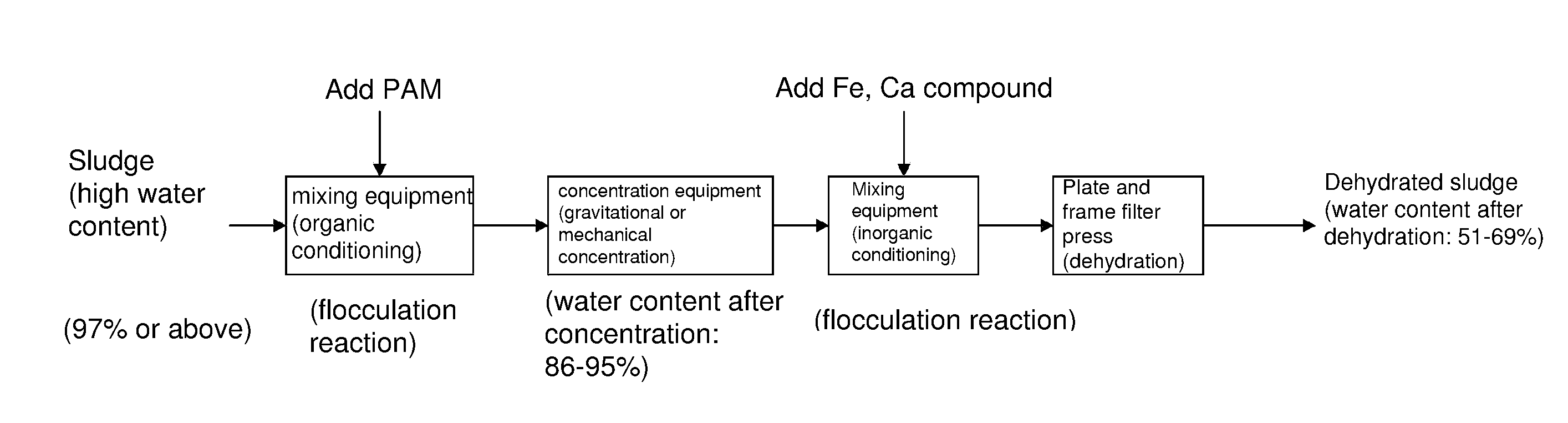
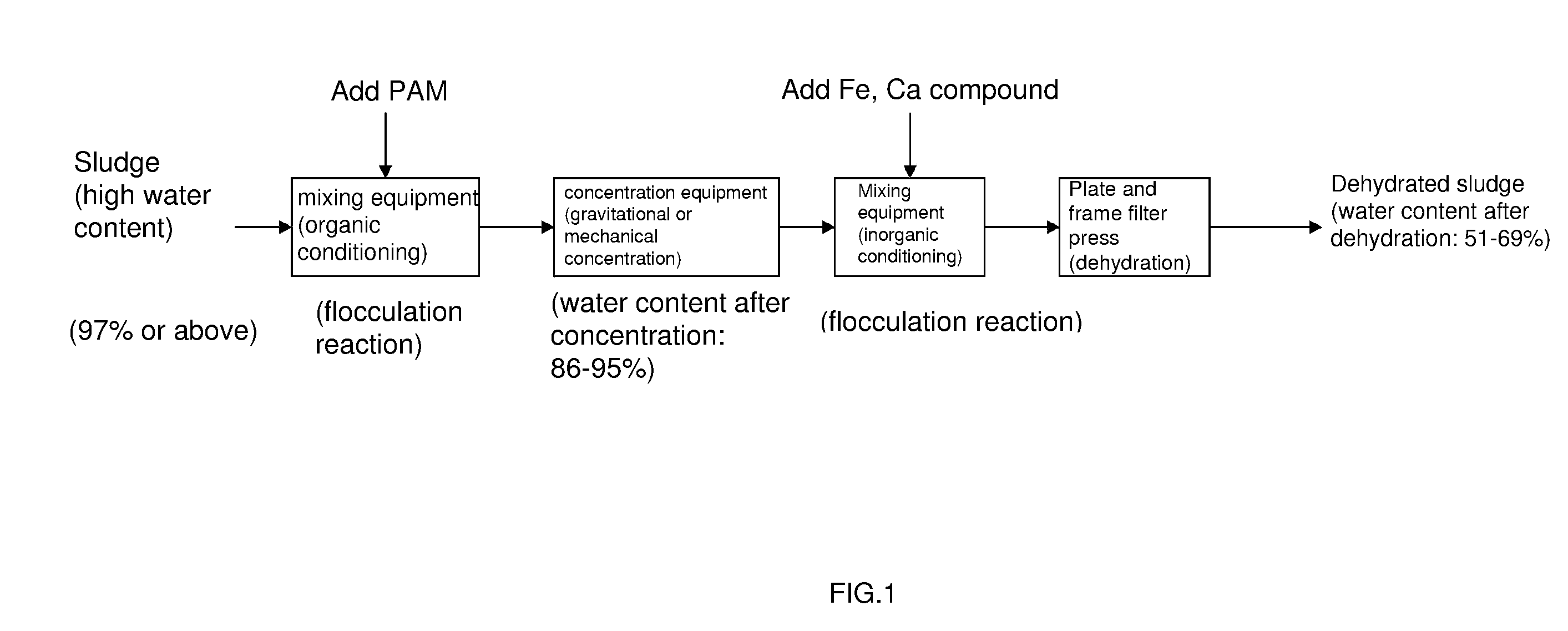
[0022]Transport the remaining sludge with a water content of 99.5% from a secondary sedimentation tank of an urban sewage treatment plant to a mixing tank, add to the sludge with an amount of polyacrylamide (PAM) equivalent to 0.12% of the mass of dry sludge, mix and blend the sludge with polyacrylamide (PAM) for full flocculation reaction to achieve the initial conditioning of the sludge, transport the conditioned sludge to a sludge concentration tank for sedimentation under gravitational force to undergo quick concentration, leave the sludge for 60 minutes for concentration, drain away the supernatant fluid formed by the water separated from the sludge out of the sludge concentration tank, pump the concentrated sludge from the bottom of the concentration tank and transport the concentrated sludge to the next procedure. Concentrated sludge at this stage contains 93% of water.

[0023]Next, the concentrated sludge is transported to a mixing tank for the further conditioning; add 1.9% o...

embodiment 2

[0024]Transport the remaining sludge with a water content of 99.7% from a secondary sedimentation tank of an urban sewage treatment plant to a mixing tank, add to the sludge with an amount of polyacrylamide (PAM) equivalent to 0.15% of the mass of dry sludge, mix and blend the sludge with polyacrylamide (PAM) for full flocculation reaction to achieve the initial conditioning of the sludge, transport the conditioned sludge to a sludge concentration tank for sedimentation under gravitational force to undergo quick concentration, leave the sludge for 120 minutes for concentration, drain away the supernatant fluid formed by the water separated from the sludge out of the sludge concentration tank, pump the concentrated sludge from the bottom of the concentration tank and transport the concentrated sludge to the next procedure. Concentrated sludge at this stage contains 90% of water.

[0025]Next, the concentrated sludge is transported to a mixing tank for the further conditioning; add 2.28%...

embodiment 3

[0026]Transport the remaining sludge with a water content of 99.3% from a secondary sedimentation tank of an urban sewage treatment plant to a mixing tank, add to the sludge with an amount of polyacrylamide (PAM) equivalent to 0.16% of the mass of dry sludge, mix and blend the sludge with polyacrylamide (PAM) for full flocculation reaction to achieve the initial conditioning of the sludge, transport the conditioned sludge to a sludge concentration tank for sedimentation under gravitational force to undergo quick concentration, leave the sludge for 120 minutes for concentration, drain away the supernatant fluid formed by the water separated from the sludge out of the sludge concentration tank, pump the concentrated sludge from the bottom of the concentration tank and transport the concentrated sludge to the next procedure. Concentrated sludge at this stage contains 90.7% of water.

[0027]Next, the concentrated sludge is transported to a mixing tank for the further conditioning; add 2.0...


PUM

PropertyMeasurementUnit
Fractionaaaaaaaaaa
Fractionaaaaaaaaaa
Fractionaaaaaaaaaa

Abstract

A sludge concentration and dehydration method is provided, which comprises the following steps: (1) add an organic agent (polyacrylamide) to the sludge for initial conditioning, then concentrate the sludge; (2) add an inorganic agent (a compound containing Fe and Ca) to the sludge for further conditioning, then transport the sludge to a dehydrator for dehydration; (3) dispose the dehydrated sludge correspondingly when it satisfies the requirements for final disposal.

Description

BACKGROUND OF THE INVENTION[0001]The present invention relates generally to a method of treating sludge, and more specifically relates to a sludge concentration and dehydration method that is capable of treating sludge with different water contents and reusing the treated sludge.[0002]The existing treatment method for sludge with different water contents generally concentrates the sludge first, then adds a conditioning agent to the sludge and thereafter dehydrates the sludge. More particularly, the sludge is first transported to a gravity concentration tank to undergo concentration; the concentrated sludge is then mixed with a conditioning agent and thereafter transported to a dehydrator to undergo dehydration. When the dehydrated sludge satisfies the requirements for final disposal, the dehydrated sludge can be disposed correspondingly. If not, the dehydrated sludge can undergo further drying treatment so that the dried sludge satisfies the requirements for final disposal and is th...

Claims


Application Information

Patent Timeline
IPC IPC(8): C02F11/12
CPCC02F1/5236C02F11/14C02F11/121C02F1/56C02F11/143C02F11/145C02F11/147
Inventor ZHONG, HUANSHENGLI, LEIWU, JIACONGWU, XUEWEISUN, ZHIMINYANG, HAIYING
Owner SWISON CREATIVE ENVIRONMENTAL SOLUTIONS CO LTD
Why Eureka
Try Eureka