
Multilayer inductor and power converter comprising it

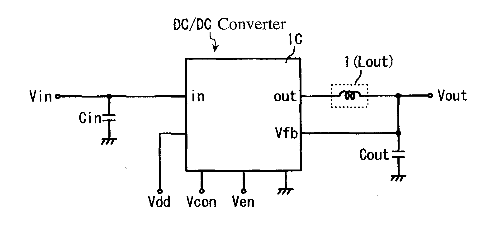
a multi-layer inductor and power converter technology, applied in the field of multi-layer inductor, can solve the problems of increasing the production difficulty of cores with lower strength, the response delay of current change, and the voltage drop of wiring, and achieves excellent dc superimposition characteristics, and good dc superimposition performan

Active Publication Date: 2010-11-11
HITACHI METALS LTD
View PDF5 Cites 31 Cited by
  • Summary
  • Abstract
  • Description
  • Claims
  • Application Information

AI Technical Summary

Benefits of technology

[0012]Accordingly, the first object of the present invention is to provide a multilayer inductor and a power converter suffering little inductance change with the temperature, and having excellent temperature characteristics of magnetic properties and excellent DC superimposition characteristics.

Problems solved by technology

The power supplies are conventionally disposed near input terminals and connected to loads of semiconductors (IC), etc., but recently problems such as response delay to current change due to the voltage reduction and current increase of semiconductors, voltage drop by wiring, and circuit impedance increase arise in a concentrated power supply system.
However, smaller wire-wound inductors make the production of cores more difficult with lower strength.
Also, because magnetic fluxes leaking from the wire-wound inductors having open magnetic circuits affect surrounding circuit devices, circuit devices cannot be disposed near the inductors, making it difficult to reduce mounting areas.
However, because wire-wound inductors occupy large areas and have large height, they are not adapted to the miniaturization of circuits by switching frequency increase.
Though this Ni ferrite has stable temperature characteristics of inductance, it is insufficient in the temperature characteristics of a saturation magnetic flux density Bs important to inductors for DC / DC converters.
Accordingly, the control of DC / DC converters by feedback current is difficult, failing to achieve stable operation.

Method used


Image

  • Multilayer inductor and power converter comprising it
  • Multilayer inductor and power converter comprising it
  • Multilayer inductor and power converter comprising it

Examples


example 1

[1] Ni Ferrite Constituting Magnetic Portion

[0090](a) Production

[0091]Main component powders comprising Fe2O3, ZnO, CuO, CoO and NiO and sub-component powders comprising SnO2 and MnO were wet-mixed, dried, and calcined at 800° C. for 2 hours. The calcined powder was charged into a ball mill with ion-exchanged water, and pulverized to a BET specific surface area of 6.5 m2 / g for about 20 hours. The pulverized calcined powder was mixed with polyvinyl alcohol, granulated by a spray drier method, molded, and then sintered at 900° C. for 2 hours in the air to form toroidal core samples each having the composition shown in Table 1, an outer diameter of 8 mm, an inner diameter of 4 mm and a thickness of 2 mm. The amounts of the main components and the sub-components were measured by X-ray fluorescence analysis and ICP optical emission spectrometry. First, the elements contained were identified by X-ray fluorescence analysis, and their amounts were quantitatively determined by a calibration ...


PUM

PropertyMeasurementUnit
temperature coefficientaaaaaaaaaa
frequencyaaaaaaaaaa

Abstract

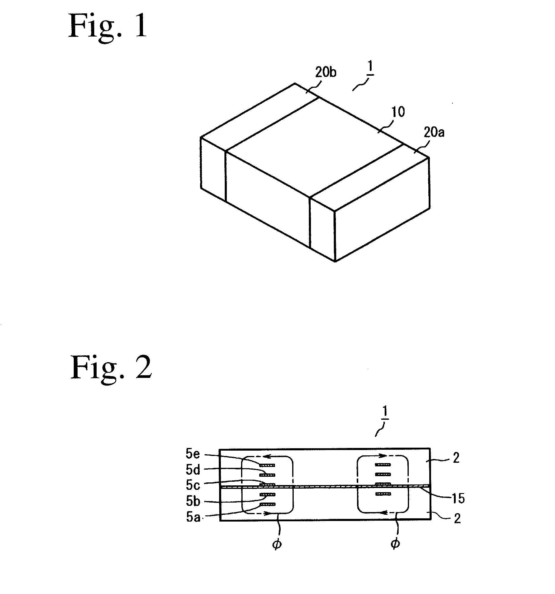
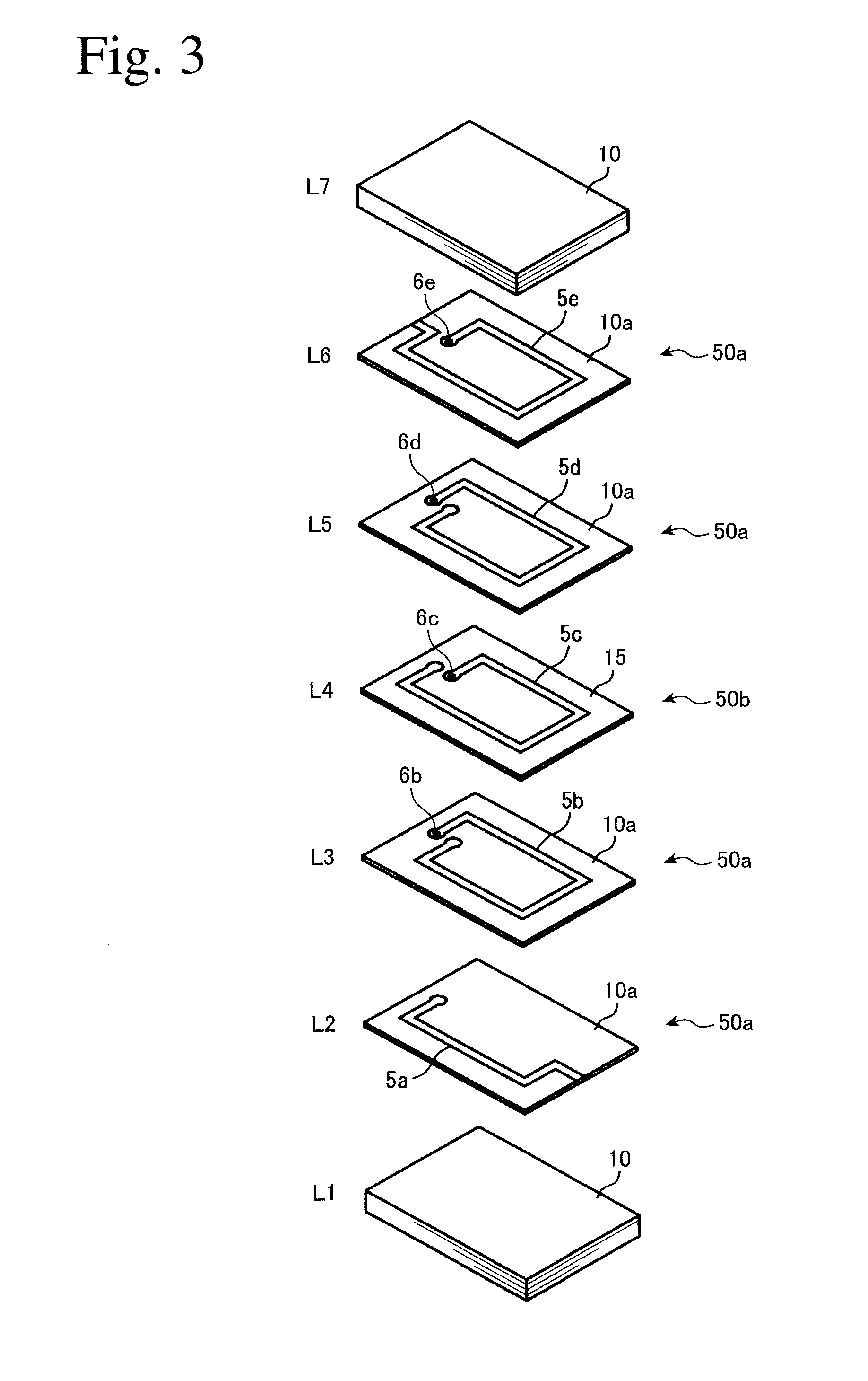
A multilayer inductor comprising a coil embedded in a magnetic portion, and a magnetic gap formed by a non-magnetic portion in part of a magnetic path, the magnetic portion being made of Ni ferrite, whose relative temperature coefficient αμir of initial permeability at a frequency of 1 MHz is more than +10 ppm / ° C. and +40 ppm / ° C. or less between −40° C. and +80° C., the non-magnetic portion being made of Zn ferrite containing more Zn than in the magnetic portion and having a Curie temperature Tc of −50° C. or lower, and the Zn content changing continuously in boundary regions between the non-magnetic portion and the magnetic portion, whereby the thickness of the magnetic gap changes with the temperature.

Description

FIELD OF THE INVENTION[0001]The present invention relates to a multilayer inductor having a magnetic gap, and a power converter comprising such a multilayer inductor.BACKGROUND OF THE INVENTION[0002]Many of various mobile electronic appliances such as cell phones, mobile information terminals PDA, note-type computers, DVD players, CD players, MD players, digital cameras, digital video cameras, etc. comprise batteries as power supplies, and DC / DC converters as power converters for converting power supply voltage to the predetermined operation voltage. The power supplies are conventionally disposed near input terminals and connected to loads of semiconductors (IC), etc., but recently problems such as response delay to current change due to the voltage reduction and current increase of semiconductors, voltage drop by wiring, and circuit impedance increase arise in a concentrated power supply system. Accordingly, a concentrated power supply system called POL (point of load), in which po...

Claims


Application Information

Patent Timeline
Patent Type & Authority Applications(United States)
IPC IPC(8): G05F3/02H01F5/00
CPCC04B35/265C04B35/6262C04B2235/3262C04B2235/3275C04B2235/3279C04B2235/3281H01F41/046C04B2235/3293C04B2235/5409H01F1/344H01F17/0013H01F17/04C04B2235/3284
Inventor TACHIBANA, TAKESHITANAKA, SATORU
Owner HITACHI METALS LTD
Learn More