Reinforcing fiber substrate of curved shape, layered product using the same, preform, fiber-reinforced resin composite material, and processes for producing those

a technology of reinforced fiber and curved shape, which is applied in the direction of weaving, other domestic articles, synthetic resin layered products, etc., can solve the problems of poor productivity, inability to correct layered products, poor productivity, etc., and achieves the improvement of circumferential properties, simple structure, and low cost.

Inactive Publication Date: 2010-11-11
TORAY IND INC
View PDF10 Cites 59 Cited by
  • Summary
  • Abstract
  • Description
  • Claims
  • Application Information

AI Technical Summary

Benefits of technology

[0073]According to the present invention, a curved reinforcing fiber substrate curved along the longitudinal direction at a predetermined shape and oriented precisely with reinforcing fibers along the curved shape at a desirable formation can be provided. Further, by using this curved reinforcing fiber substrate as at least one reinforcing fiber layer and layering a plurality of reinforcing fiber layers, a dry curved reinforcing-fiber layered product oriented with reinforcing fibers precisely at a desirable formation as a whole can be provided. Further, a process for producing a curved reinforcing-fiber layered product capable of producing such a curved reinforcing-fiber layered product with a desirable formation efficiently for a short time can be provided.
[0074]Further, by using the above-described curved reinforcing-fiber layered product, a preform having a flange portion and the like and precisely formed in a predetermined cross-sectional shape can be provided. Further, a process for producing a preform capable of forming such a preform with a desirable formation efficiently in a predetermined cross-sectional shape for a short time can be provided. Further, a process for producing a preform can also be provided which, using a device with a simple structure and capable of being constructed inexpensively, such a preform with a desirable formation can be formed as preform with a predetermined cross-sectional shape smoothly and easily without generating problems such as wrinkles, even for a sectional shape for forming whose direct...

Problems solved by technology

In the three-dimensional fiber structural body disclosed in Patent document 1, because the sector plate-like yarn layer is formed using a jig of truncated cone for arranging fiber bundles, it takes a long time to form a curved yarn layer, and therefore, there is a problem that the productivity is bad.
Further, because a plurality of yarn layers are bound by thickness-direction yarns, additional time is further required for the binding, and if the layered product is taken out from the fiber bundle arranging jig of truncated cone, there is also a problem that a waviness, originating from a difference between inner and outer circumferential length of the truncated cone ascribed to the thickness of the layered product, occurs (namely, when the layered product taken out from the fiber bundle arranging jig of truncated cone is placed on a table whose upper surface is flat at a condition being expanded in a flat-plate like form, because arc wave shapes along the outer surface of the truncated cone of the fiber bundle arranging jig are left in the layered product at a condition where they are connected to each other, there occurs a problem that the layered product cannot be corrected into a flat-plate formation (a flat-plate formation having a curved shape at a planar condition)).
Further, in the process for producing a curved fiber-reinforced composite structural member disclosed in Patent document 2, because the respective reinforcing fiber layers are layered in order and at the same time of the la...

Method used


Image

  • Reinforcing fiber substrate of curved shape, layered product using the same, preform, fiber-reinforced resin composite material, and processes for producing those
  • Reinforcing fiber substrate of curved shape, layered product using the same, preform, fiber-reinforced resin composite material, and processes for producing those
  • Reinforcing fiber substrate of curved shape, layered product using the same, preform, fiber-reinforced resin composite material, and processes for producing those

Examples


example 1

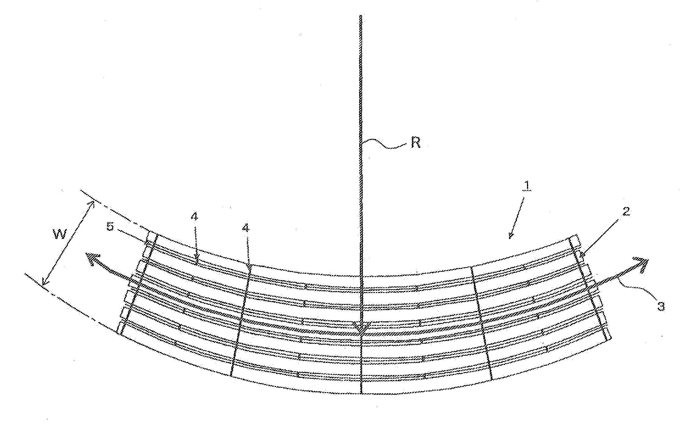
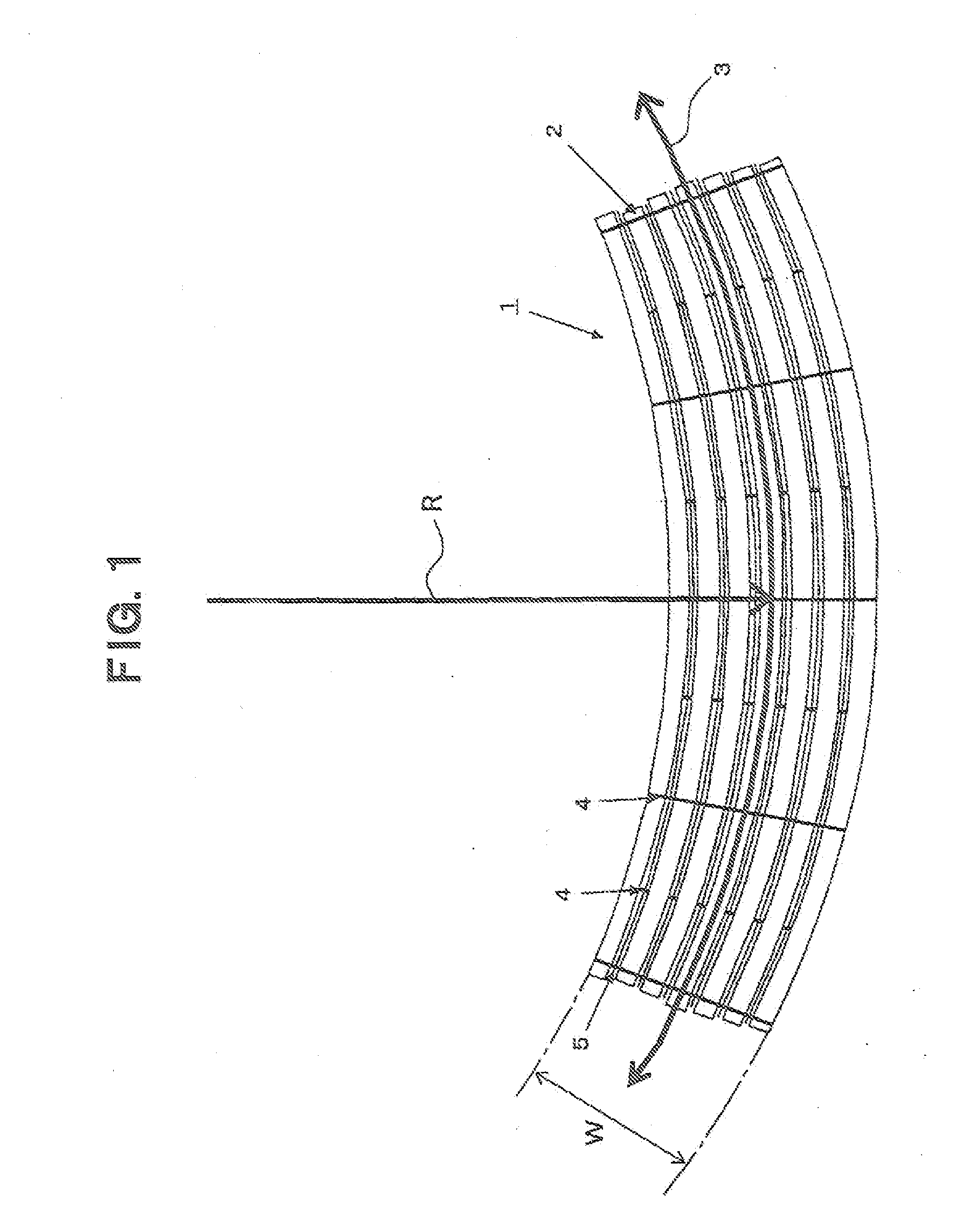
[0237]Using a weaving machine for curved reinforcing fiber substrate 161 shown in FIG. 21, a 0° oriented curved reinforcing fiber substrate 162 arranged with reinforcing fiber yarns in the circumferential direction of the curved shape shown in FIG. 1 was prepared. The shape of the substrate was 3 m in radius of curvature R, 200 mm in width of substrate, and 4.7 m in length. As shown in FIG. 21, the weaving machine for curved reinforcing fiber substrate 161 is constructed from healds 165, 166 and a reed 167 for reinforcing fiber yarns163 and auxiliary warp yarns 164, a weft yarn threading mechanism 169 for inserting auxiliary weft yarns 168, and upper, lower and intermediate mandrels 170, 171, 172. At a rear position of these mandrels, a resin material scattering device 173 and a infrared ray heater (not shown) at a further rear position are attached, resin particles 174 scattered on the woven curved reinforcing fiber substrate 162 are heated and the particles can adhere to the curve...

example 2

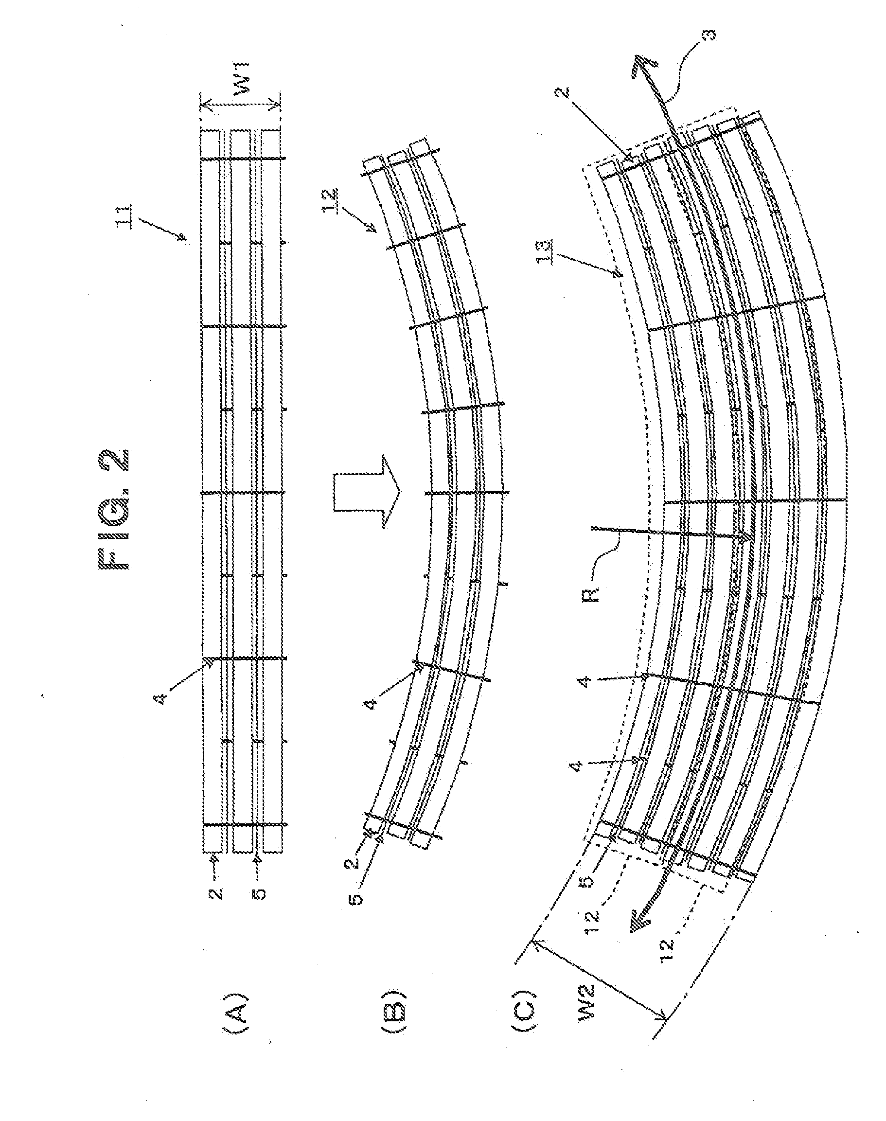
[0240]Using the same materials as those in Example 1, a unidirectional reinforcing fiber woven fabric with a width of 1 m was woven wherein the prepared reinforcing fiber yarns were arranged in one direction in parallel to each other and so as to extend linearly, the auxiliary warp yarns were arranged between the reinforcing fiber yarns in parallel to each other, and the auxiliary weft yarns were arranged so as to be substantially perpendicular to the reinforcing fiber yarns and the auxiliary warp yarns. The resin material was scattered on the surface of the unidirectional reinforcing fiber woven fabric so that the weight of the resin material became 27 g / m2, and using an infrared ray heater, the surface temperature of the curved reinforcing fiber substrate was heated at 180° C. to make the resin material adhere thereto. Using this unidirectional reinforcing fiber woven fabric, a 90° oriented curved reinforcing fiber substrate as shown in FIG. 3 (C) was prepared.

[0241]First, by cu...

example 3

[0243]The unidirectional reinforcing fiber woven fabric with a width of 1 m and having an NCW structure prepared in Example 2 was prepared. By cutting the unidirectional reinforcing fiber woven fabric in 45° direction relative to the arrangement direction of the reinforcing fiber yarns and further cutting between the reinforcing fiber yarns for every 12 reinforcing fiber yarns, 56 sheets of reinforcing fiber yarn bundles each having 12 reinforcing fiber yarns and having a width of 200 mm as shown in FIG. 4 were prepared. All the reinforcing fiber yarn bundles were adjusted in gaps between reinforcing fiber yarn bundles, and were arranged and coupled along the curved shape in the longitudinal direction of the curved shape so that the reinforcing fiber yarns were not overlapped and the gaps did not become 3 mm or more, to prepare a 45° oriented curved reinforcing fiber substrate with a width of 200 mm and length of 4.7 m. In a similar manner, −45° oriented curved reinforcing fiber sub...


PUM

PropertyMeasurementUnit
Angleaaaaaaaaaa

Abstract

A curved reinforcing fiber substrate having a curved planar shape comprising a plurality of reinforcing fiber yarns arranged parallel to a direction along a circumferential direction of the curved shape, and auxiliary weft yarns arranged in directions crossing the plurality of reinforcing fiber yarns each arranged in one direction of the circumferential direction.

Description

TECHNICAL FIELD OF THE INVENTION[0001]The present invention relates to a curved reinforcing fiber substrate having a curved shape along a longitudinal direction, a layered product using the curved reinforcing fiber substrate, a preform formed using the layered product, a fiber-reinforced resin composite material molded using the preform, and processes for producing those efficiently.BACKGROUND ART OF THE INVENTION[0002]Fiber-reinforced resin composite materials are broadly known as light materials high in strength and stiffness. In case where a relatively long fiber-reinforced resin composite material is molded, in order to ensure a high strength or stiffness in a target direction, a structure is frequently employed wherein a layered product is formed by layering a plurality of reinforcing fiber layers whose orientation directions of reinforcing fibers are set at respective predetermined directions. Although there is a case of employing a layered product with a formation of a prepre...

Claims


Application Information

Patent Timeline
IPC IPC(8): D04H3/04B32B5/28B29C70/20D03D41/00D03D3/00D04H5/10
CPCB29B11/16B29C70/226B29C70/342D04H5/10B32B5/12B32B27/04D04H3/04B29L2031/003B29C70/50B32B5/022B32B5/024B32B5/22B32B5/26B32B3/28B32B2260/023B32B2260/046B32B2262/02B32B2262/0261B32B2262/0269B32B2262/0276B32B2262/101B32B2262/106B32B2307/50B32B2307/718B32B2605/18B29D99/0003
Inventor SHINODA, TOMOYUKIKIBE, RYUZOYAMAMOTO, KOHNOSUKE
Owner TORAY IND INC
Why Eureka
Try Eureka