Preparation process for preventing deformation of jelly-roll type electrode assembly

Active Publication Date: 2010-11-11
LG ENERGY SOLUTION LTD
View PDF5 Cites 58 Cited by
  • Summary
  • Abstract
  • Description
  • Claims
  • Application Information

AI Technical Summary

Benefits of technology

[0018]The organic/inorganic composite layer includes microfine pores to provide thickness flexibility, which in turn, exhibits favorable buffer effects when the electrode is expanded. The microfine pore may be

Problems solved by technology

However, since this assembly is generally fabricated by winding a cathode and an anode under a compact condition, which each has an extended sheet form, to constitute a structure in a cylindrical or elliptical shape so that stress generated by expansion and contraction of an electrode during charge/discharge may be accumulated in the electrode assembly and, if such stress accumulation exceeds a constant limit, the electrode assembly may become deformed.
For this reason, a gap between adjacent electrodes is irregular so that performance of a battery having the electrodes may be rapidly deteriorated and internal short-circuit may occur, causing a problem of threatening safety of the battery.
However, such an organic/inorganic composite porous membrane fabricated according to any conventional technique described above may cause the following problems when the membrane is adopted for a jell-roll type electrode assembly, although the membrane may be useful for a stack/folding type electrode assembly.
However, during removal of the mandrel, due to friction between the membrane, which was positi

Method used


Image

  • Preparation process for preventing deformation of jelly-roll type electrode assembly
  • Preparation process for preventing deformation of jelly-roll type electrode assembly
  • Preparation process for preventing deformation of jelly-roll type electrode assembly

Examples


example 1

1.1. Preparation of Electrode Sheet

[0082]A cathode sheet was fabricated by adding 95 wt. % of lithium cobalt oxide (LiCoO2) as a cathode active material, 2.5 wt. % of Super-P (a conductive material), 2.5 wt. % of PVdF (a binder) to N-methyl-2-pyrrolidone (NMP) as a solvent to prepare a cathode mixture slurry, and then, applying the slurry to both sides of an aluminum foil, drying and compressing the same.

[0083]An anode sheet was fabricated by adding 95 wt. % of graphite as an anode active material, 1.5 wt. % of Super-P (a conductive material), 3.5 wt. % of PVdF (a binder) to NMP to prepare an anode mixture slurry, and then, applying the slurry to both sides of a copper foil, drying and compressing the same.

1.2. Preparation of Organic / Inorganic Composite Porous Membrane

[0084]An organic / inorganic composite porous membrane was fabricated by the following procedure. Firstly, 5 wt. % of polyvinylidenefluoride-chlorotrifluoroethylene (PVdF-CTFE) copolymer was added to acetone as a first s...

experimental example 1

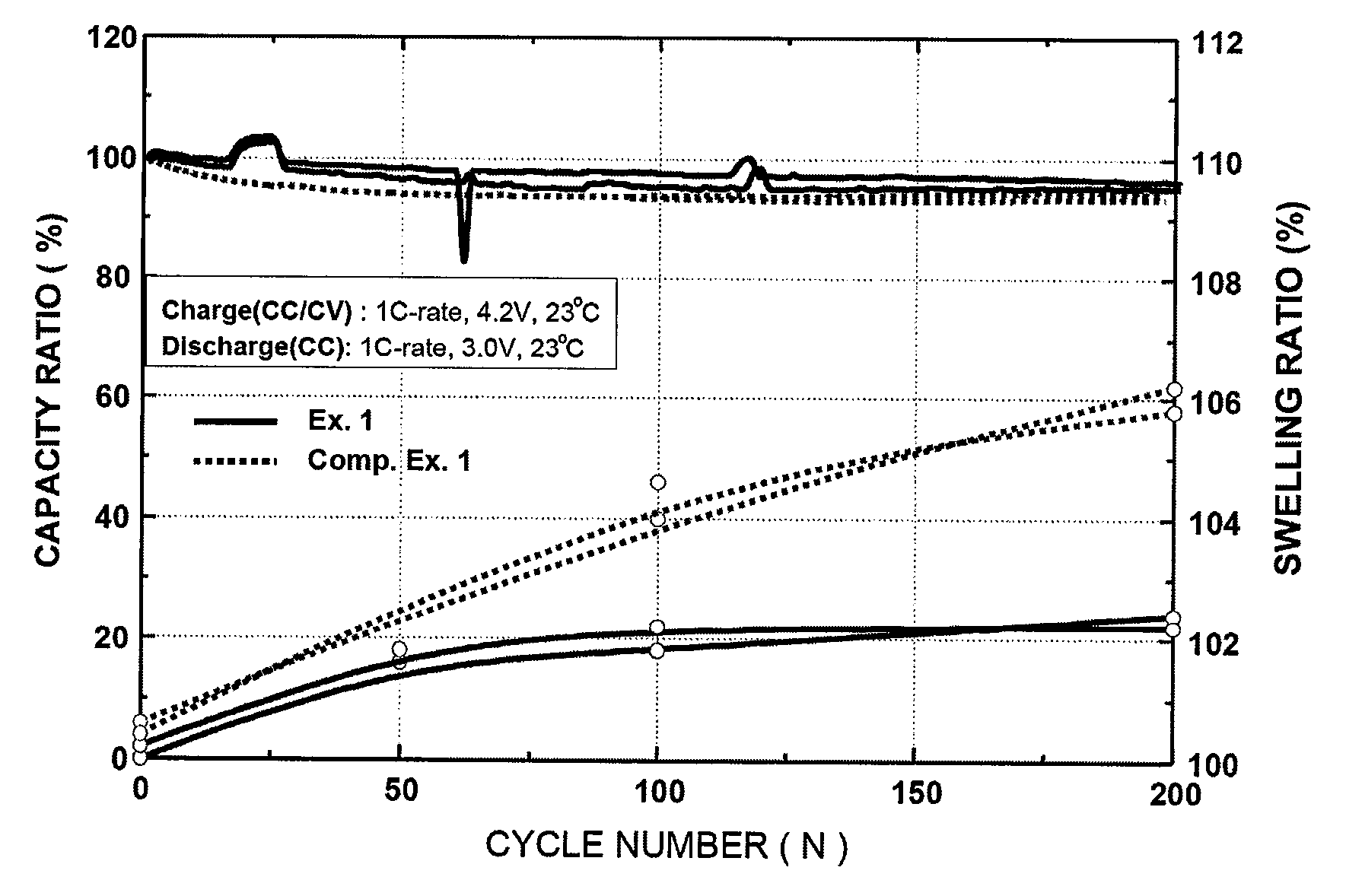
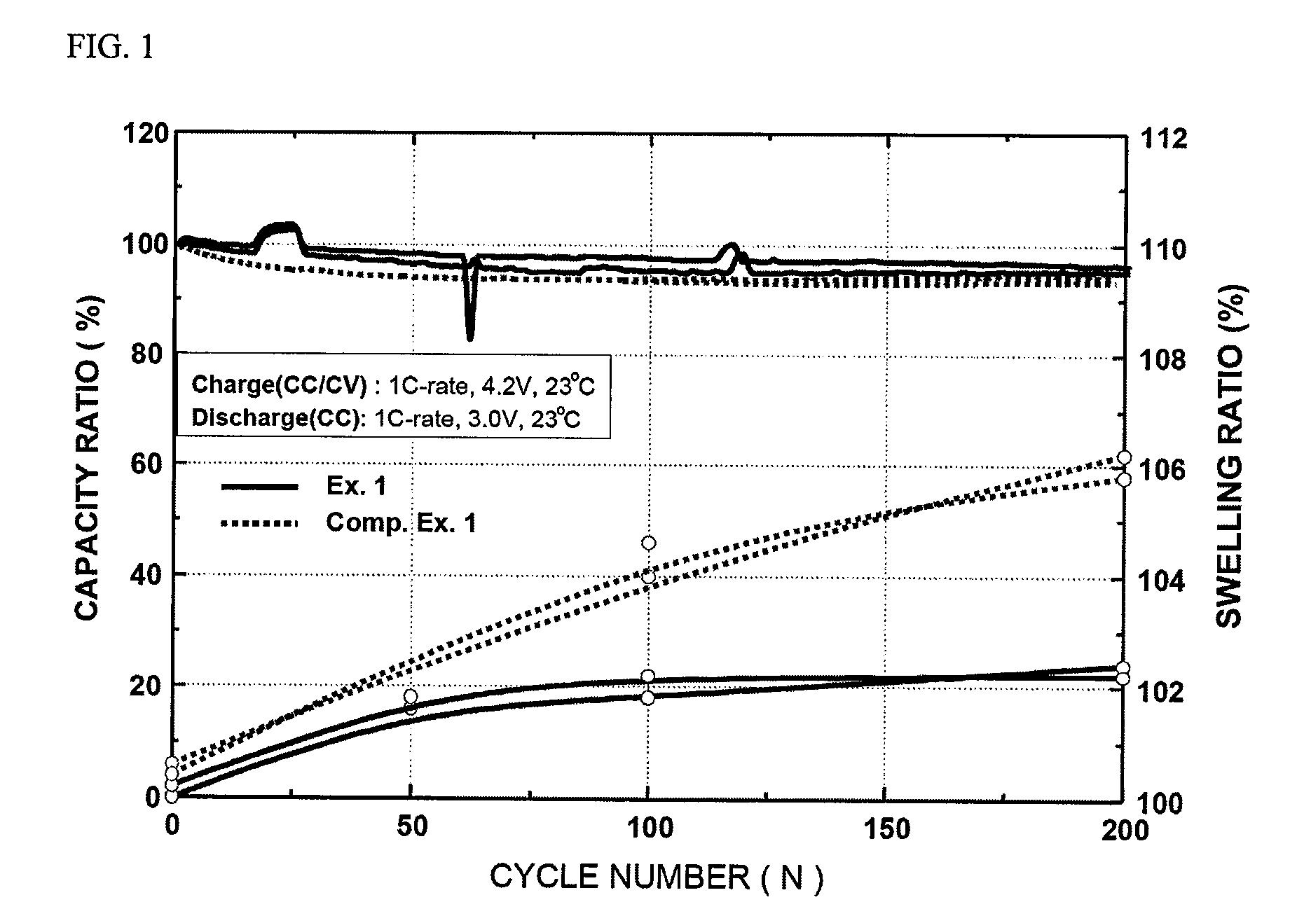
[0088]In order to compare and determine differences in cycle characteristics and swelling properties of two batteries fabricated in Example 1 and Comparative Example 1, respectively, 500 charge / discharge cycles were conducted under charge / discharge conditions shown in FIG. 1 and capacity ratios and swelling extents were determined. The results are shown in FIG. 1.

[0089]As illustrated in FIG. 1, it was found that the battery fabricated according to Example 1 has cycle characteristics substantially corresponding to those of the battery fabricated according to Comparative Example 1. More particularly, both of the batteries of Example 1 and Comparative Example 1 substantially maintained the same discharge capacity. Therefore, it may be understood that the present inventive battery of Example 1 exhibited no decrease in discharge capacity, although it had a separation membrane having an organic / inorganic composite layer.

[0090]On the other hand, a swelling ratio of the battery of Example 1...

experimental example 2

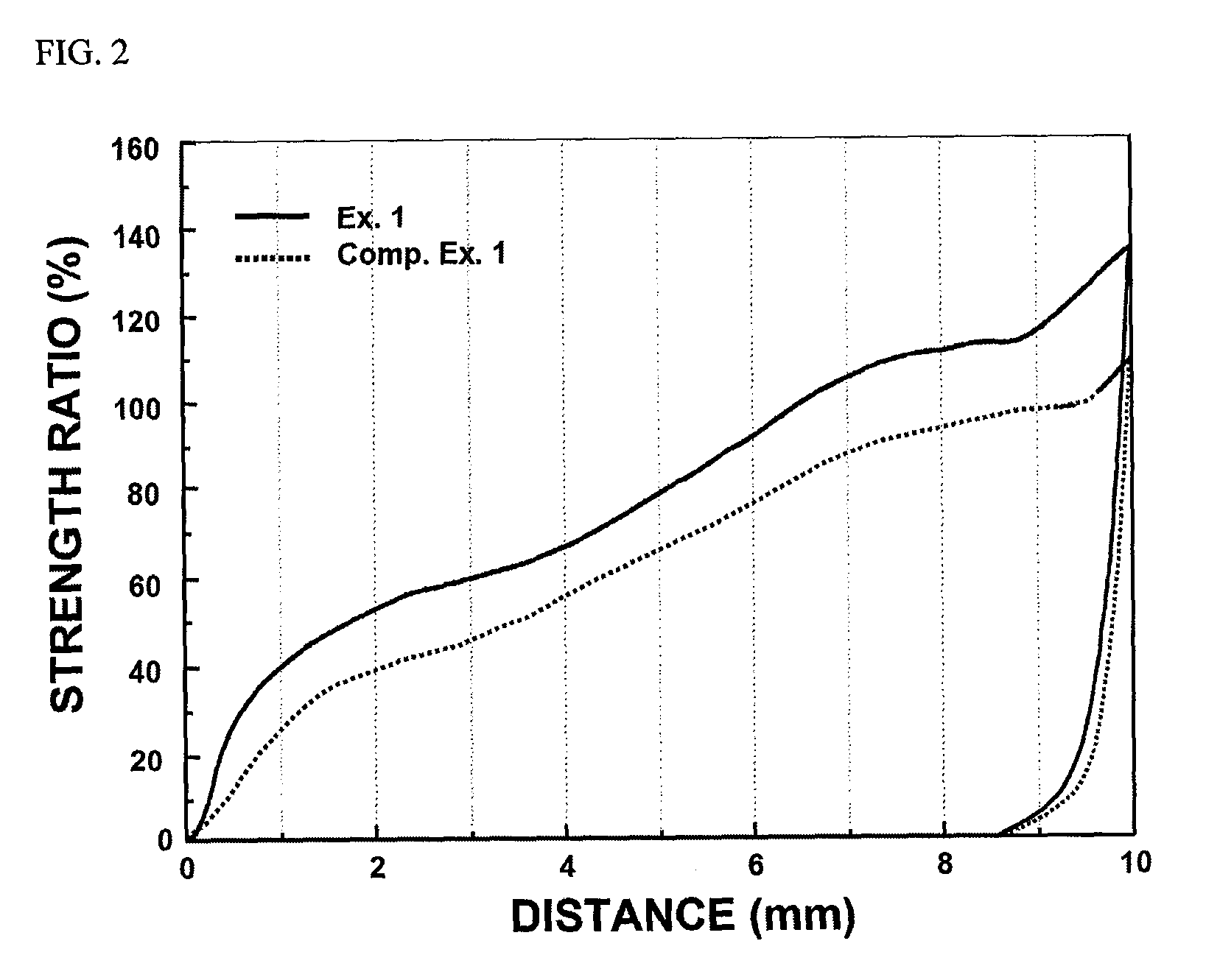
[0091]In order to evaluate a mechanical strength of a battery, the batteries fabricated in Example 1 and Comparative Example 1 were subjected to bending strength measurement (using a texture analyzer) so as to determine a piercing strength. The results are shown in FIG. 2.

[0092]As illustrated in FIG. 2, the present inventive battery of Example 1 exhibited greater than 30% higher strength than the battery of Comparative Example 1. The reason behind these results may be that the mechanical strength of the battery was improved by inorganic particles in the organic / inorganic composite coating layer.

[0093]Although the preferred embodiments of the present invention have been disclosed for illustrative purposes, those skilled in the art will appreciate that various modifications, additions and substitutions are possible, without departing from the scope and spirit of the invention as disclosed in the accompanying claims.


PUM

PropertyMeasurementUnit
Lengthaaaaaaaaaa
Thicknessaaaaaaaaaa
Diameteraaaaaaaaaa

Abstract

Provided is a method for fabrication of a jelly-roll type electrode assembly having a cathode/separation membrane/anode laminate structure, including: (a) coating both sides of a porous substrate with organic/inorganic composite layers, each of which includes inorganic particles and an organic polymer as a binder, so as to fabricate a composite membrane; and (b) inserting one end of a sheet laminate comprising a cathode sheet and an anode sheet as well as the composite membrane into a mandrel, winding the sheet laminate around the mandrel, and then, removing the mandrel, wherein the organic/inorganic composite layer includes microfine pores capable of moderating a variation in volume during charge/discharge of a secondary battery and an interfacial friction coefficient between the composite membrane and the mandrel is not more than 0.28.

Description

FIELD OF THE INVENTION[0001]The present invention relates to a process for fabrication of a jelly-roll type electrode assembly having a lamination structure of cathode / separation membrane / anode and, more particularly, a process for fabrication of a jelly-roll type electrode assembly, including (a) preparing a composite membrane in which an organic / inorganic composite layer containing inorganic particles and an organic polymer as a binder is applied to both sides of a porous substrate; and (b) inserting one end of a sheet laminate comprising the composite membrane, a cathode sheet and an anode sheet into a mandrel, winding the sheet laminate around the mandrel, and removing the mandrel, wherein the organic / inorganic composite layer may have microfine pores capable of moderating (or reducing) a variation in volume during charge / discharge of a secondary battery and an interfacial friction coefficient (μ) between the composite membrane and the mandrel may be 0.28 or less, as well as a c...

Claims


Application Information

Patent Timeline
IPC IPC(8): H01M6/10H01M4/82H01M6/04H01M10/0525H01M10/0565H01M10/0587H01M10/36H01M50/119H01M50/121H01M50/124
CPCH01M2/0275H01M2/0287H01M2/166H01M2/1673H01M10/0409H01M10/0431Y10T29/49115H01M10/0565H01M10/0587H01M10/4235Y02E60/12Y10T29/49108H01M10/0525H01M50/124H01M50/446H01M50/46H01M50/119H01M50/121Y02E60/10Y02P70/50H01M4/04
Inventor YUN, YOUNGKWANGRYU, SANGBAEKLEE, JINSOOKIM, SOORYOUNGCHOI, BYUNGJINLEE, HYANG MOK
Owner LG ENERGY SOLUTION LTD
Why Eureka
Try Eureka