High Efficiency Dual Cycle Internal Combustion Steam Engine and Method

Active Publication Date: 2010-12-02
THERMAL POWER RECOVERY
View PDF99 Cites 22 Cited by
  • Summary
  • Abstract
  • Description
  • Claims
  • Application Information

AI Technical Summary

Benefits of technology

[0012]In accordance with the invention, the coolant in the cooling jacket of a dual cycle internal combustion steam engine is intentionally maintained at an elevated temperature preferably of at least about 225° F. but which typically range from about 240° F.-300° F. or more. Most preferably, a non-aqueous liquid coolant is used together with a provision for controlling the flow rate and residence time of the coolant within the cooling jacket to maintain the temperature of the coolant at a selected elevated temperature that is substantially above the boiling point of water, but below the boiling points of the coolant. The non-aqueous liquid coolant having a boiling point above 212° F. and more preferably above 225° F. serves as a thermal interface between two thermodynamic cycles of energy conversion, e.g., either diesel or Otto cycle and a Rankine cycle. Through the operation of these provisions working together in a coordinated manner as will be described, a much greater fraction of the unused thermal energy can be recovered than would otherwise be possible. More specifically, the invention enables a much greater amount of the coolant heat to be transferred to a steam expander that is provided as a part of an internal combustion piston engine.
[0013]The invention also takes advantage of the differential cylinder temperature distribution that occurs as a result of the combustion and gas expansion. The greater wall and head temperatures peculiar to combustion are located near the top one-third of the cylinder, whereas the lower temperatures associated with gas expansion are located in the bottom two-thirds of the cylinder. The present invention provides a cooling jacket design that is tailored to extract heat at the highest possible temperature from each heat transfer zone most preferably by having the coolant follow a circuitous pathway of a selected configuration that will be described to achieve more efficient and improved heat transfer from the combustion chamber to the cooling medium and, hence, greater heat transfer to a vaporizable working fluid used in the steam expander.

Problems solved by technology

Meanwhile, increasing fuel prices and shortages mount steadily as world supplies of fossil fuel decline and greenhouse gas emissions continue to rise.
The Rankine cycle has been used to recover waste heat from internal combustion engines, but power recovery has been inefficient and has suffered from various other shortcomings.
However, steam turbines have not proved efficient in units under 500 HP, have had gear box problems and cannot accelerate rapidly thus making them impractical for use in vehicles such as cars and trucks.
Within the engine itself, cooling problems can be caused by an inability to provide coolant capable of robust heat transfer to the feed water or by steam generation hot spots, which may result in an uncontrolled heating condition in certain parts of the engine due to what is known as transition film boiling, a form of runaway heating that follows nucleate boiling often leading to damage from pre-ignition or detonation in the combustion chamber.
Consequently, successful waste heat recovery in an IC engine presents unique problems especially if high fuel efficiency is to be achieved together with reliable operation in which there is little likelihood of a burnout or detonation in the combustion chamber.

Method used


Image

  • High Efficiency Dual Cycle Internal Combustion Steam Engine and Method
  • High Efficiency Dual Cycle Internal Combustion Steam Engine and Method
  • High Efficiency Dual Cycle Internal Combustion Steam Engine and Method

Examples


example 1

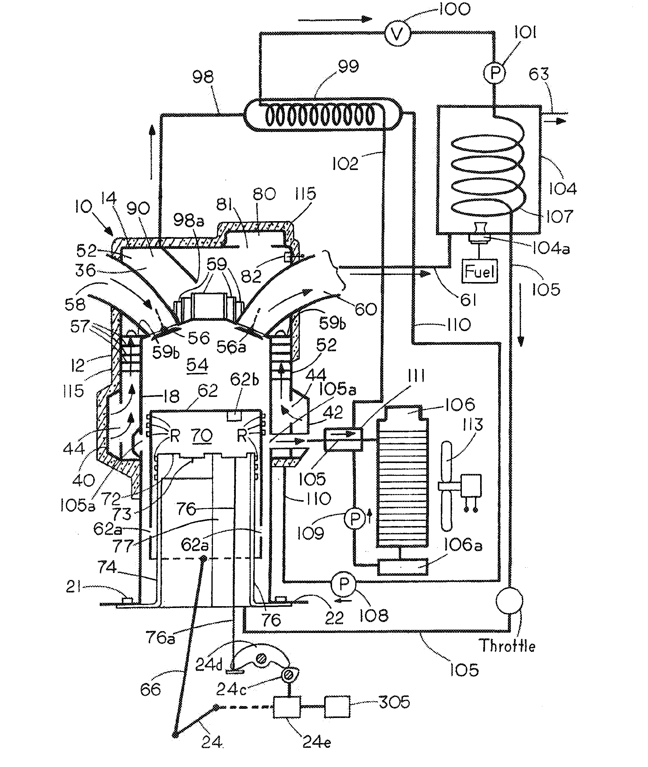
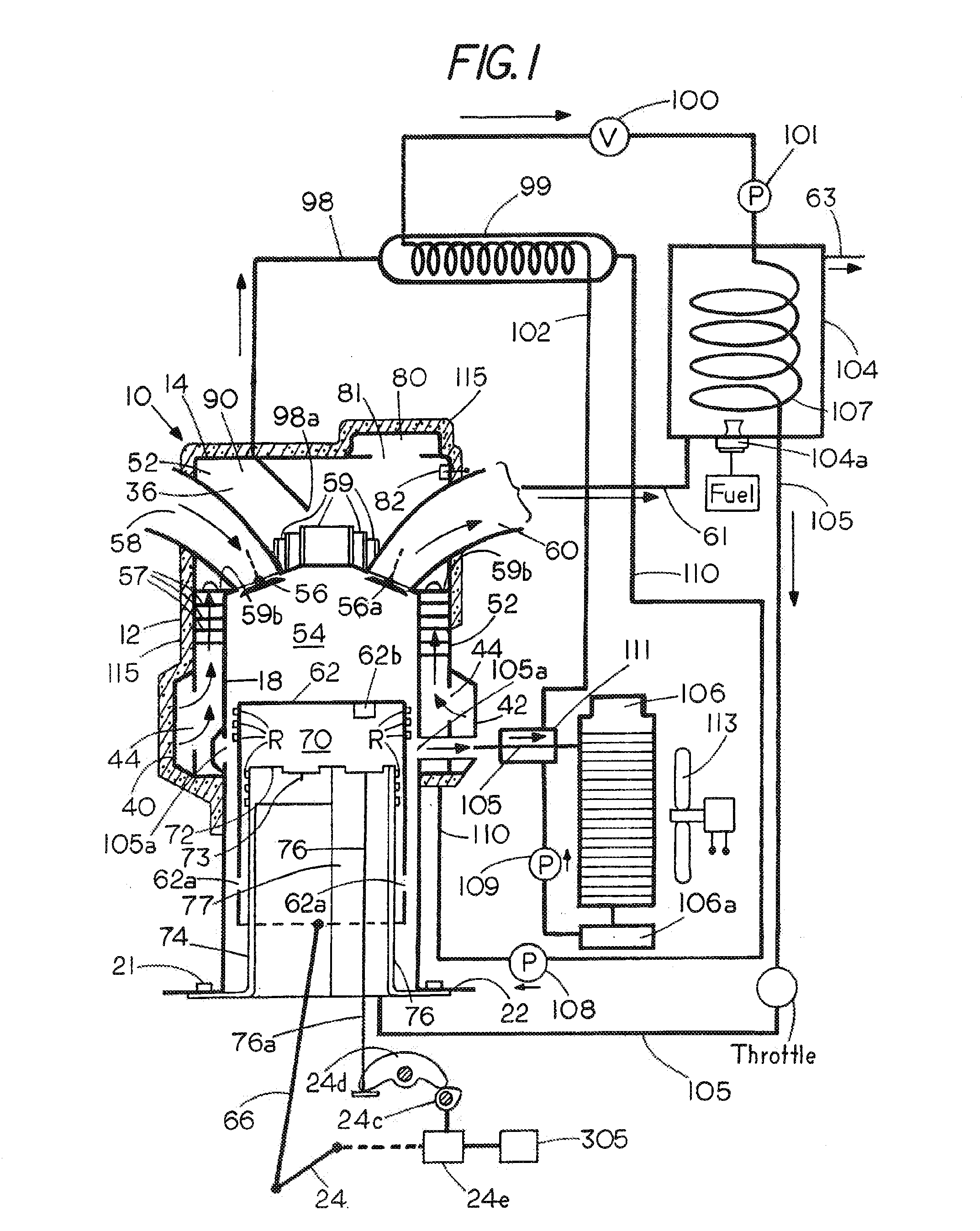
[0032]A one cylinder I.C. engine having a bore of 96 mm and a stroke of 78 mm was tested and found at 5994 rpm to produce a coolant flow of 4330 lb / hr which translated into an energy transfer rate of 27022 Btu / hr (ΔT of 6.24° F.). With an eight percent steam cutoff as a fraction of the steam power stroke, the combustion exhaust gases in generator 104 were sufficient to sustain a water evaporation rate of 313 lb / hr for steam at 800° F. and 800 psia, The pumps 28 and 108 and / or a coolant thermostat (not shown) are intentionally regulated by the central engine management computer 305 (FIG. 1) to raise the coolant temperature to 250° F. The feed water in tank 109 is at 200° F. Using a heat exchanger 99 that is able to provide an efficiency of 80% so as to heat the feed water to 240° F. (200° F.+80% of 50° F.), the heat absorbed from coolant equals 40° F.×313 lb / hr or 12520 Btu / hr which amounts to about 46% (12520÷27022) of the coolant heat having been transferred to feed water. The rema...

example 2

[0033]In a second run otherwise similar to Example 1 at 2996 rpm, coolant flow was 2646 lb / hr that translated to an energy transfer rate of 34148 Btu / hr (ΔT of 12.9° F.). Exhaust gas provided sufficient heat for the superheater 104 to sustain an indicated water evaporation rate of 156 lb / hr. Heated by coolant at 300° F. in a heat exchanger 99 of 80% efficiency to 280° F. (200+80% of 100° F.), the 200° F. feed water absorbs 80° F.×156 lb / hr or 12480 Btu / hr which is about 36% (12480÷34148) of the coolant heat. The exhaust gases in this run provided another 28000-33000 Btu / hr to the steam generator 104.


PUM


Abstract

The coolant in the cooling jacket of a dual cycle internal combustion steam engine is intentionally maintained at an elevated temperature that may typically range from about 225° F.-300° F. or more. A non-aqueous liquid coolant is used to cool the combustion chamber together with a provision for controlling the flow rate and residence time of the coolant within the cooling jacket to maintain the temperature of the coolant at a selected elevated temperature that is substantially above the boiling point of water but below the boiling point of the coolant. The coolant is passed from the jacket through a heat exchanger in a first circuit to transfer heat to a vaporizable working fluid such as water and is then returned. An optional second intrajacket perturbation circuit within the engine can be used to disrupt and disperse pockets of vapor that may tend to form before damaging hot spots can develop around the combustion chamber. A cooling jacket design is tailored to extract heat at the highest possible temperature from each heat transfer zone as by having the coolant follow a circuitous helical pathway to achieve more efficient and improved heat transfer from the combustion chamber to the cooling medium.

Description

[0001]This application is a continuation-in-part of Ser. No. 12 / 539,987, filed Aug. 12, 2009, which is a continuation-in-part of Ser. No. 12 / 492,773, filed Jun. 26, 2009 (abandoned) which is a continuation-in-part of Ser. No. 12 / 387,113, filed Apr. 28, 2009, which is a continuation-in-part of Ser. No. 12 / 075,042, filed Mar. 7, 2008[0002]The applicant claims the benefit of pending provisional application Ser. No. 61 / 228,752, filed Jul. 27, 2009; Ser. No. 60 / 905,732, filed Mar. 7, 2007; Ser. No. 61 / 192,254, filed Sep. 17, 2008; Ser. No. 61 / 320,959, filed Apr. 10, 2010; Ser. No. 61 / 194,608, filed Sep. 29, 2008; and Ser. No. 61 / 309,640, filed Mar. 2, 2010.BACKGROUND OF THE INVENTION[0003]This invention relates to dual cycle engines, and more particularly to a dual cycle internal combustion piston engine and method wherein engine coolant and exhaust gases are used to produce steam that is applied to the piston for recovering waste combustion heat.[0004]While the internal combustion engin...

Claims


Application Information

Patent Timeline
IPC IPC(8): F01K17/00
CPCF01B7/20F01B17/04F01B21/02F02B41/00Y02T10/142Y02T10/14Y02T10/16Y02T10/166F02B75/30Y02T10/12
Inventor HARMON, SR., JAMES V.PEOPLES, JERRY A.
Owner THERMAL POWER RECOVERY
Why Eureka
Try Eureka