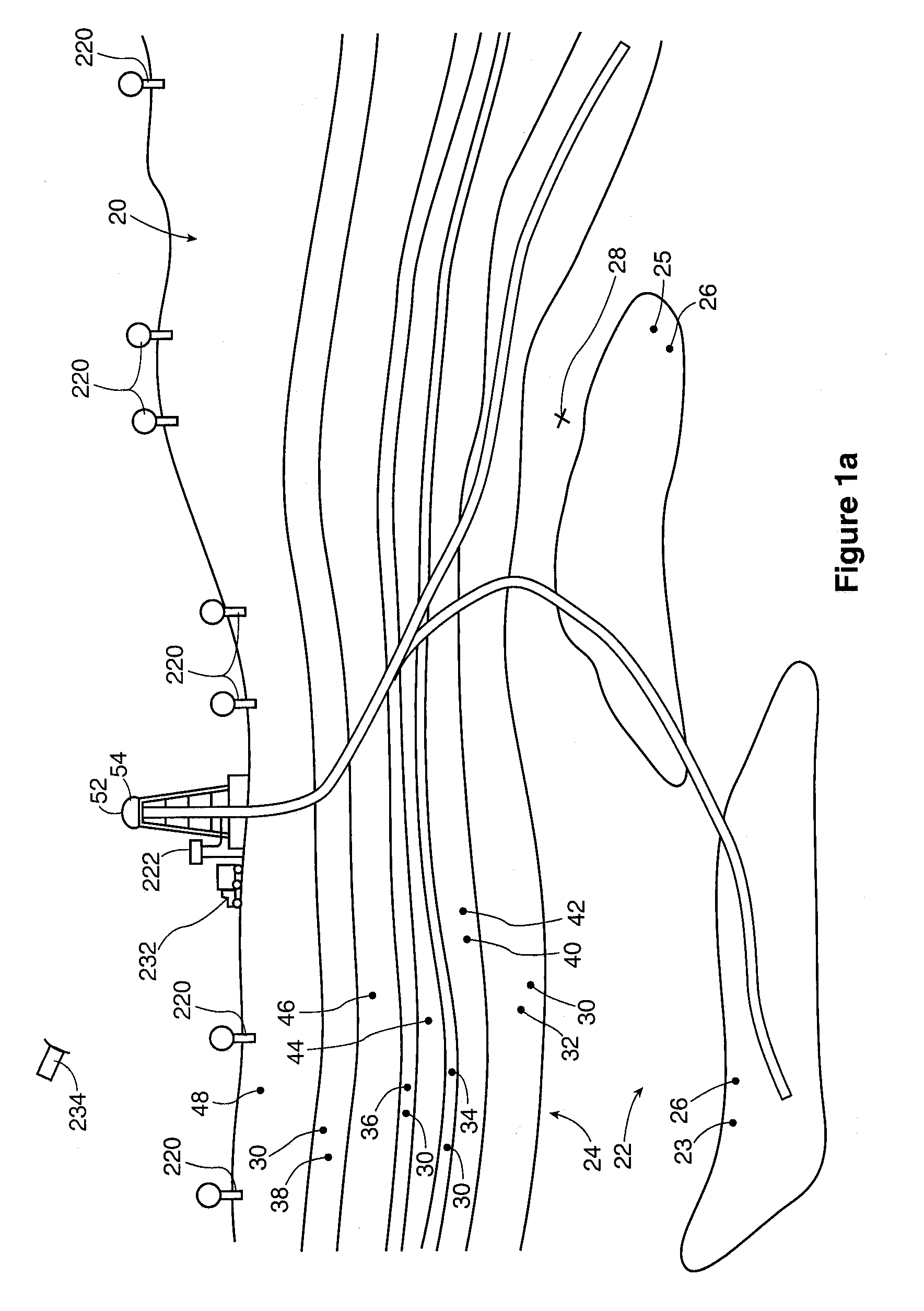
Given the non-homogeneity of the underlying
geological structure, and the tendency for drill bits to wander, it may be difficult to know with reasonable accuracy precisely where the
drill bit may be.
(a) The drilling operation, and
mud motor life, may be optimized by the
real time transmission of, and adjustment of drilling operations in response to, measurement data of natural gamma rays, borehole inclination, borehole pressure, resistivity of the formation and,
mud motor bearing temperature, and weight on the bit.
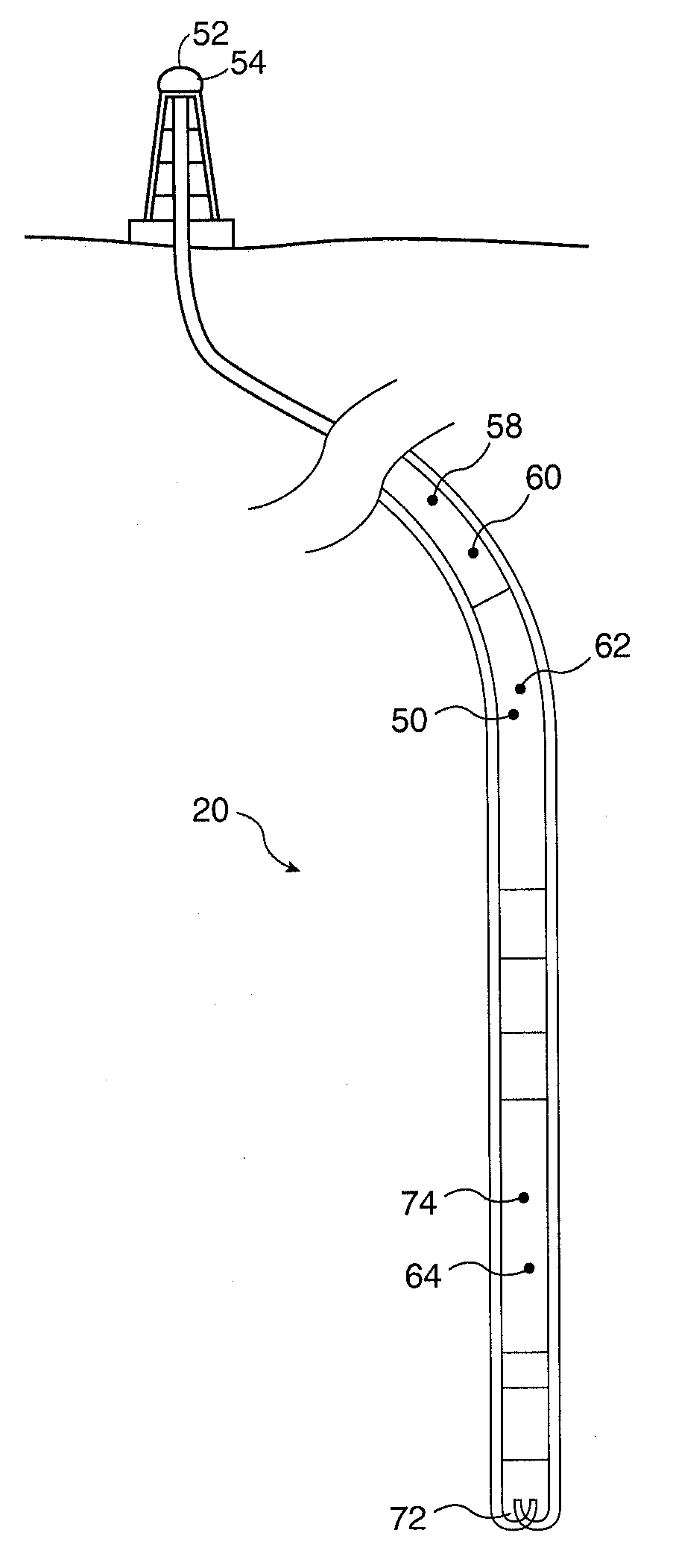
(b) When used with a downhole motor, the mud pulse
telemetry system is typically located above the
mud motor so that it is spaced a substantial distance from the drilling bit to protect the electronic components from the effects of vibration. As a result, the measured
environmental data may not necessary correlate with the actual conditions at the drilling bit. A conventional
telemetry system may have a depth
lag (i.e., a distance offset) of up to or greater than 60 feet. It is possible to drill out of a
hydrocarbon producing formation before detecting the exit, resulting in the need to drill several meters of borehole to get back into the pay zone. The interval drilled outside of the pay zone results in lost production revenue and may include wasted costs for completing that non-producing interval.
(c) Near bit sensor systems have been developed to provide
early detection of changes to the formation while drilling, but may still be located a spaced distance from the drill bit
assembly, giving a
lag in determination of formation changes. Mounting sensors in a mud motor may be very costly and may reduce
system reliability.
(d) Systems permitting relatively
high rate, bi-directional,
data transmission have been developed for sending data to the surface through an electrical line. However, a
drill string wireline or cable is subject to stress at
pipe connections; may be prone to wear, damage or destruction during normal drilling operations; and may be somewhat unreliable and prone to failure.
(e) Systems have also been developed for the downhole generation and transmission of acoustic or seismic signals or
waves through the
drill string or surrounding formation. However, a relatively large amount of downhole power is typically required to generate sufficient
signal strength for surface detection. A relatively large power source must be provided or repeaters can be used at intervals along the string to boost the
signal as it propagates.
Lack of such information can lead to severe “dogleg” paths along the borehole resulting from hole or drill path corrections to find or to reenter the payzones.
Such
wellbore profiles usually limit the horizontal reach and the final
wellbore length exposed to the reservoir.
Steering efficiency and geological positioning are considered in the industry among the greatest limitations of the current drilling systems for drilling horizontal and complex wellbores.
Prior art downhole lack in providing such information during drilling of the boreholes”.
Resistivity measurements do not provide
bed boundary information relative to the downhole subassembly.
Furthermore, error margin of the depth-measuring devices, usually deployed on the surface, is frequently greater than the depth of investigation of the resistivity devices.
The optimal placement of the borehole is thus very difficult to obtain based on the currently available MWD measurements, particularly in thin pay zones, dipping formation and complex
wellbore designs.”
It is well known that mud pulse systems are intrinsically limited to a few bits per second due to attenuation and spreading of pulses.”
It has been found, however, that this type of system requires a special
drill pipe and special tool joint connectors which substantially increase the cost of a drilling operation.
Also, these systems are prone to failure as a result of the
abrasive conditions of the mud system and the wear caused by the rotation of the drill string.”
It has been found, how ever, that the very low intensity of the signal which can be generated downhole, along with the acoustic
noise generated by the
drilling system, makes signal detection difficult.
Reflective and refractive interference resulting from changing diameters and thread makeup at the tool joints compounds the signal attenuation problem for
drill pipe transmission.”
It has been found, however, that in deep or noisy well applications, conventionals electromagnetic systems are unable to generate a signal with sufficient intensity to be recovered at the surface.”
As the ratio drops, it becomes more difficult to recover or reconstruct the signal.
While increasing the power of the transmitted signal is an obvious way of increasing the
signal to noise ratio, this approach is limited by batteries suitable for the purpose and the desire to extend the time between battery replacements.
“
Wireline acoustic technology has been particularly difficult to adapt to MWD applications.
In addition to road
noise generated by the drilling
assembly dragging against the wall of the borehole, there is an additional source of
noise generated by the rotation of the drill bit and the drill string.
Further, the slotted isolation sub technique used to isolate transmitters and receivers in
wireline applications can not be used in MWD applications in that such slots would mechanically weaken the MWD acoustic subassembly to the failing point.
This problem is compounded when other types of sensors, comparable in sophistication to corresponding wireline applications, are run in combination with
full wave acoustic devices.
As an example, it is not feasible using current MWD
telemetry capacity to transmit simultaneously a plurality of full
acoustic wave forms or
gamma ray energy spectra or electromagnetic wave attenuation and phase shift data, or a combination thereof, to the surface for
processing to determine parameters of interest at depth intervals sufficient to obtain the required vertical resolution of the penetrated formations.
Furthermore, it is not feasible to store copious amounts of
raw data downhole sensor data for subsequent retrieval and
processing due to relatively limited storage capacity of current MWD systems.
There may be
abrasive and reactive fluids.
Equipment used to drill rock may be subject to unhelpfully harsh shock and
vibration spectra.
Consequently, the use of electrical sensing and telecommunication equipment and electrical connections in a downhole environment may not always work well.
Second, the sensing equipment may tend to be relatively fragile, and so may tend to be placed behind the mud motor in a
coiled tubing system.
Further, it may be difficult to send acoustic signals in an acoustically noisy environment given the very significant
noise generation of the bit itself.

