System and Method for Ion Implantation with Improved Productivity and Uniformity

a technology of ion beam and ion beam, which is applied in the field of ion beam productivity and uniformity improvement, can solve the problems of change in ion beam properties, such as current or size, across the scan path, and the ratio of the wafer area implanted with desired properties to the total wafer area, so as to increase the beam current, increase the overall productivity, and increase the beam uniformity

Active Publication Date: 2010-12-09
AXCELIS TECHNOLOGIES
View PDF8 Cites 28 Cited by
  • Summary
  • Abstract
  • Description
  • Claims
  • Application Information

AI Technical Summary

Benefits of technology

[0006]The present invention is directed to an ion implantation system configured to reduce the effect of zero field effects (ZFE) (e.g., thereby increasing beam uniformity) while increasing overall productivity. One particular aspect of the invention provides a method comprising introducing a neutralizing injected gas (e.g., Argon, Xenon) into a beam line to primarily affect a region comprising a magnetic scanner. More particularly, an injected gas is introduced into a beam line, raising the pressure of an ambient vacuum around the magnetic scanner, to enhance (e.g., increase) the beam current (e.g., increase the neutralization) or density of the magnetized ion beam (e.g., an ion beam at regions where the scanning magnetic field is non-zero) thereby providing a uniform beam current. The injected gas may improve beam current or density by enhancing (e.g., increasing, decreasing) charge neutralization of the magnetized beam (e.g., the ion beam at regions where the scanning magnetic field is non-zero) thereby reducing the current loss due to the ZFE (e.g., through charge neutralization). By reducing the current loss in regions having a magnetic field, the magnetized beam current or density is enhanced (e.g., the beam current or density is increased in regions where the magnetic field is non-zero) raising the overall beam current in a uniform manner over an entire scan path and thereby reducing the effect of the ZFE. In other words, the ZFE is effectively mitigated by an increase in the magnetized beam current or density.

Problems solved by technology

Beam blowup, occurring differently along different paths through the beam line, may cause a change of ion beam properties, such as current or size, across the scan path.
If these non-uniformities are not corrected the workpiece may be implanted non-uniformly and wafer yield (i.e. the ratio of wafer area implanted with desired properties to total wafer area) may suffer.

Method used


Image

  • System and Method for Ion Implantation with Improved Productivity and Uniformity
  • System and Method for Ion Implantation with Improved Productivity and Uniformity
  • System and Method for Ion Implantation with Improved Productivity and Uniformity

Examples


Embodiment Construction

[0019]The present invention will now be described with reference to the drawings wherein like reference numerals are used to refer to like elements throughout.

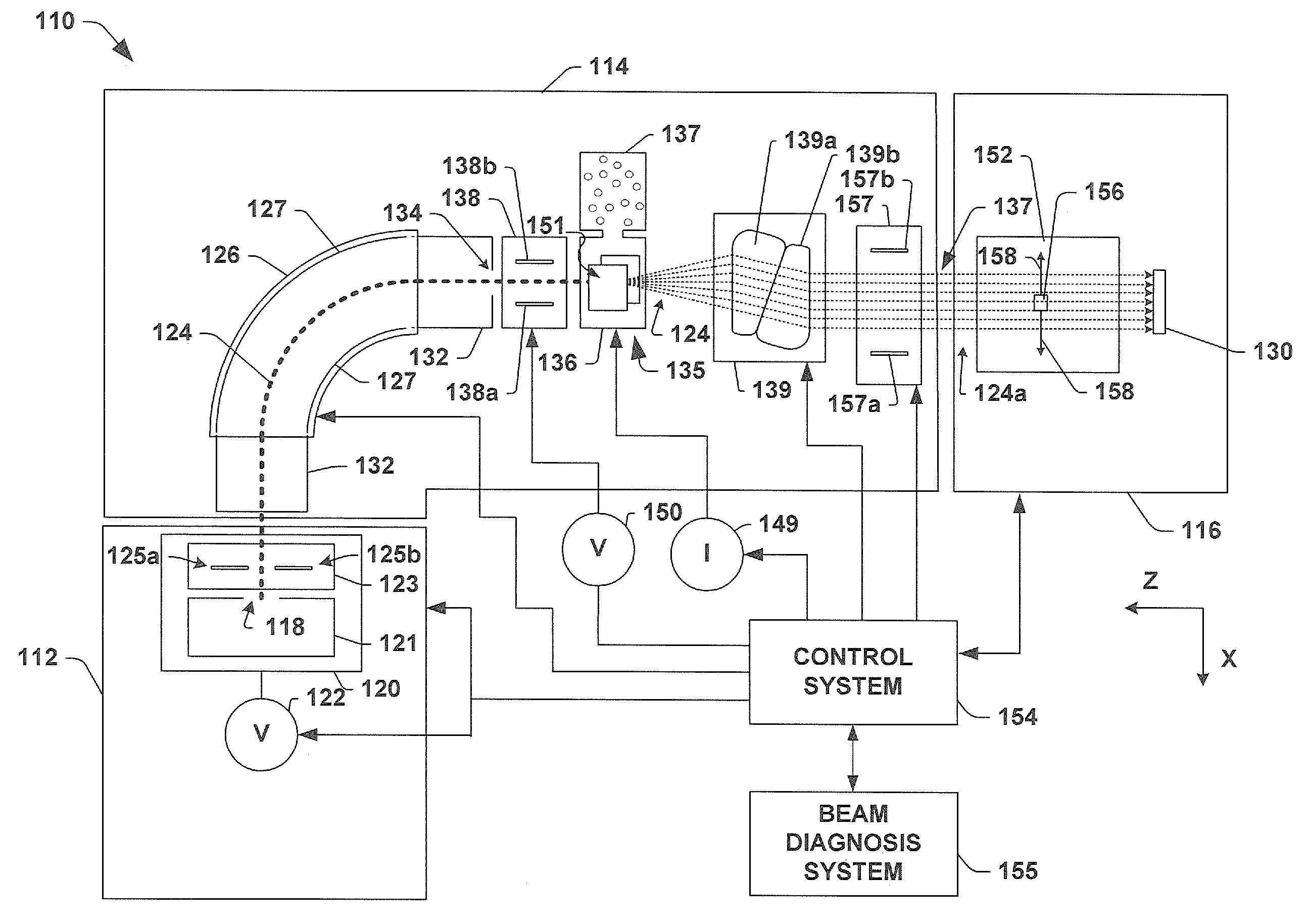
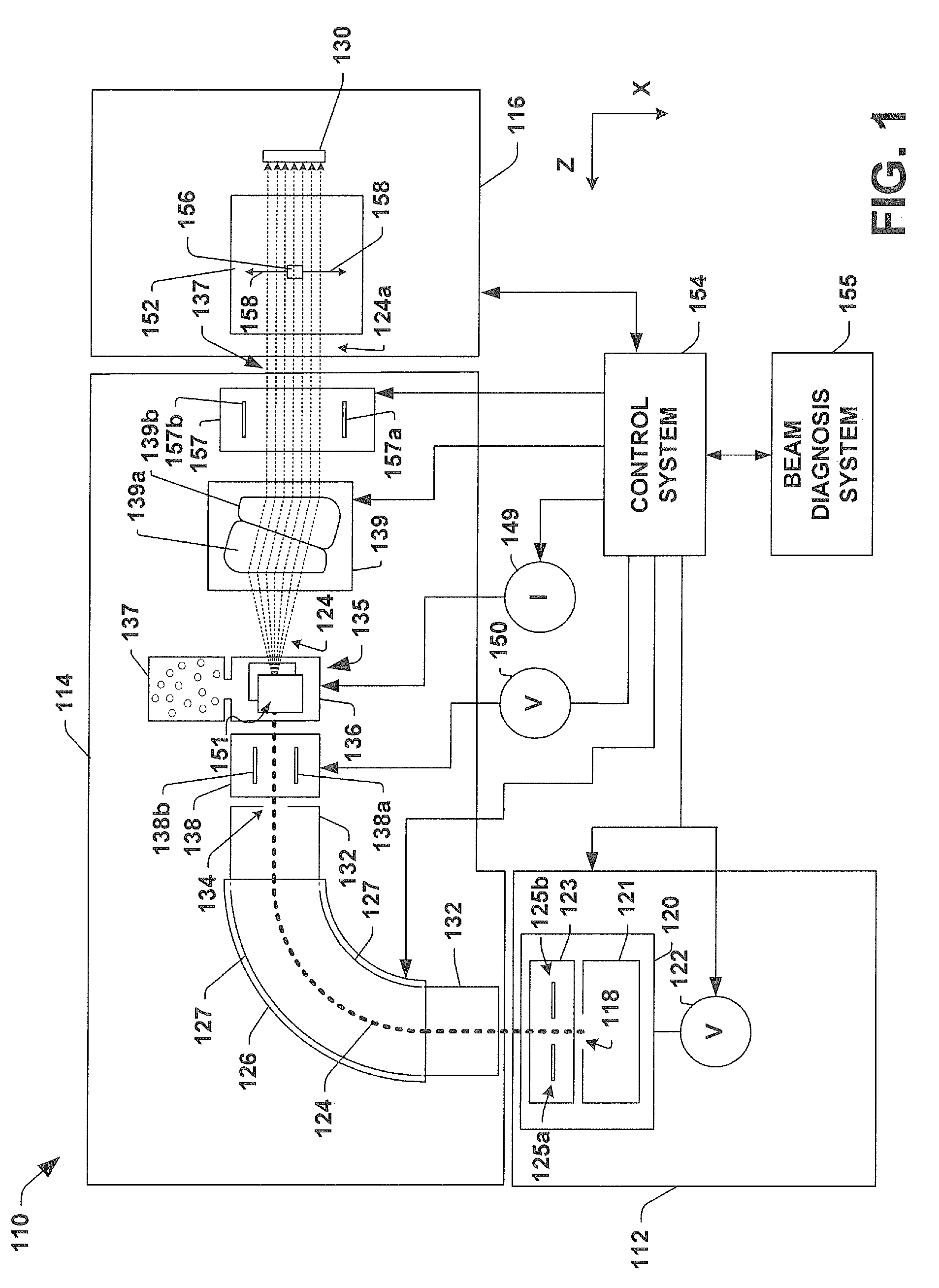
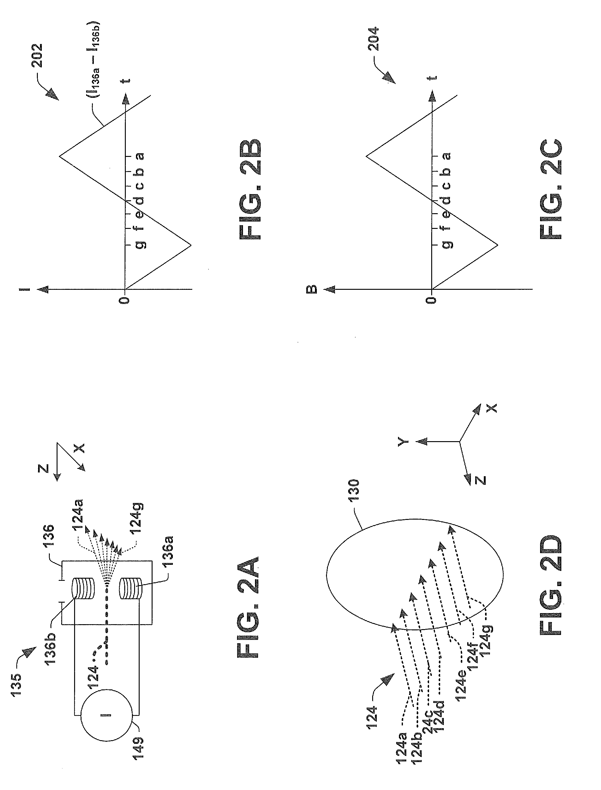
[0020]Ion implanters (e.g., hybrid scan ion implanters) may rely upon magnetic scanners to effectively scan an ion beam over the surface of a workpiece. Magnetic scanners in particular have been found to cause a detrimental time-dependent space charge effect on ion beams often referred to as the zero field effect (ZFE) or the zero field anomaly (ZFA). The zero field effect relates to a sudden change (e.g., drop, rise) in beam current when the magnitude of a scanning magnetic field approaches zero. If the beam scan velocity cannot be modulated sufficiently fast, or if the beam shape change causes the part of the workpiece that is implanted by the beam suffering the ZFE to be implanted differently, the implant can result with detrimental non-uniformity on a workpiece.

[0021]The exact cause of the zero field effect is not clear, h...


PUM


Abstract

A method comprising introducing an injected gas (e.g., Argon, Xenon) into a beam line region comprising a magnetic scanner is provided herein. The injected gas improves beam current by enhancing (e.g., increasing, decreasing) charge neutralization of the magnetic ion beam (e.g., the ion beam at regions where the scanning magnetic field is non-zero) thereby reducing the current loss due to the zero field effect (ZFE). By reducing the current loss in regions having a magnetic field, the magnetic beam current is increased (e.g., the beam current is increased in regions where the magnetic field is non-zero) raising the overall beam current in a uniform manner over an entire scan path and thereby reducing the effect of the ZFE. In other words, the ZFE is removed by effectively minimizing it through an increase in the magnetized beam current.

Description

FIELD OF THE INVENTION[0001]The present invention relates generally to ion implantation systems, and more specifically to methods and apparatus for improving productivity and uniformity of a magnetically scanned ion beam.BACKGROUND OF THE INVENTION[0002]In the manufacture of semiconductor devices, ion implantation is often used to dope semiconductor workpieces (e.g., silicon wafers) with impurities. For example, ion implanters or ion implantation systems may treat a workpiece with an ion beam, to produce n-type or p-type doped regions or to form passivation layers on the workpiece. When used for doping semiconductors, the ion implantation system injects a selected ion species to produce the desired extrinsic material.[0003]Since the size of a workpiece is often greater than the size of an ion beam, hybrid scan ion implanters are often employed to enable an ion beam to scan over a surface of a workpiece. Hybrid scan ion implanters rely upon a time varying electric or magnetic field t...

Claims


Application Information

Patent Timeline
Patent Type & Authority Applications(United States)
IPC IPC(8): H01J37/317H01J3/32H01J37/147H01J49/26
CPCH01J37/147H01J37/244H01J37/3171H01J37/317H01J2237/006H01J2237/182H01J2237/24542H01J49/30
Inventor VANDERBERG, BO H.HAYS, STEVEN C.RAY, ANDY
Owner AXCELIS TECHNOLOGIES
Why Eureka
Try Eureka