
Multi-element amplitude and phase compensated antenna array with adaptive pre-distortion for wireless network

a wireless network and antenna array technology, applied in the field of communication systems and components, can solve the problems of increasing the weight and wind load of the newly installed antenna array, significant restrictions on the tolerance and accuracy of mechanical phase shifters, and requiring substantial amounts of relatively expensive dielectric materials and rigid mechanical support, so as to achieve high efficiency and maximize gain. the effect of high efficiency mod

Inactive Publication Date: 2010-12-09
INTEL CORP
View PDF10 Cites 79 Cited by
  • Summary
  • Abstract
  • Description
  • Claims
  • Application Information

AI Technical Summary

Benefits of technology

[0017]It is an object of the present invention to provide a variable beam tilt adjustable antenna employing adaptive predistortion with high efficiency power amplifier modules to achieve linear signal amplification and beam forming.
[0018]In carrying out these and other objectives, features, and advantages of the present invention, a variable beam tilt, RF power amplifier enabled, antenna array is provided for a wireless network system.

Problems solved by technology

This requires significant restrictions of the tolerance and the accuracy of a mechanical phase shifter to provide required signal division between various radiating elements over various elevation plane angle settings.
Hence, the weight and wind loading of the newly installed antenna array cannot increase significantly.
Generally, highly accurate mechanical phase shifter implementations require substantial amounts of relatively expensive dielectric materials and rigid mechanical support.
Such construction techniques result in an increased assembly volume, weight, and manufacturing costs.
Additionally, mechanical phase shifter configurations that have been developed utilizing lower cost materials may fail to provide adequate passive intermodulation suppression under high power RF signal levels.
Consequently, due to these design limitations, unwanted upper side lobe suppression at different down tilt angles may occur.
Adding controlled amplitude variation to a high power phase shifter is problematic and further complicates its implementation.
Generating a required angle of electrical tilt from a shared antenna has thus far resulted in compromises in the performance of the antenna.
This effect is unavoidable and happens in all antenna designs.
Such configuration is highly inefficient as individual RF amplifier outputs are attenuated due to losses associated with cavity combiners, duplexers, and the tower cable run connecting amplifier output to the an antenna.
However, tower cable run losses and duplexer losses are still present and must be accounted.
Modern cellular systems employ complex, digitally modulated RF signals which tend to require highly linear PA operation.
Unfortunately, there is performance tradeoff between linearity and efficiency in PAs as highly linear operating class PAs (Class A for example) tend to be least power efficient when compared to similarly capable Class AB.
Additionally, highly efficient amplifiers are required for tower mounted operation since conventional forced air cooling techniques add bulk and reduce reliability (as fans tend to fail when exposed to elements).
In previous attempts, keeping a PA operating in high efficiency operation was found difficult to achieve due to dynamic nature of amplified signals, further being complicated by the antenna beam tilting.
However, this has been very difficult to achieve since practical phase shifters exhibit insertion loss variation over the range phase shift settings thus introducing RF signal division inaccuracies—contributing to the increased side lobe levels.

Method used


Image

  • Multi-element amplitude and phase compensated antenna array with adaptive pre-distortion for wireless network
  • Multi-element amplitude and phase compensated antenna array with adaptive pre-distortion for wireless network
  • Multi-element amplitude and phase compensated antenna array with adaptive pre-distortion for wireless network

Examples


Embodiment Construction

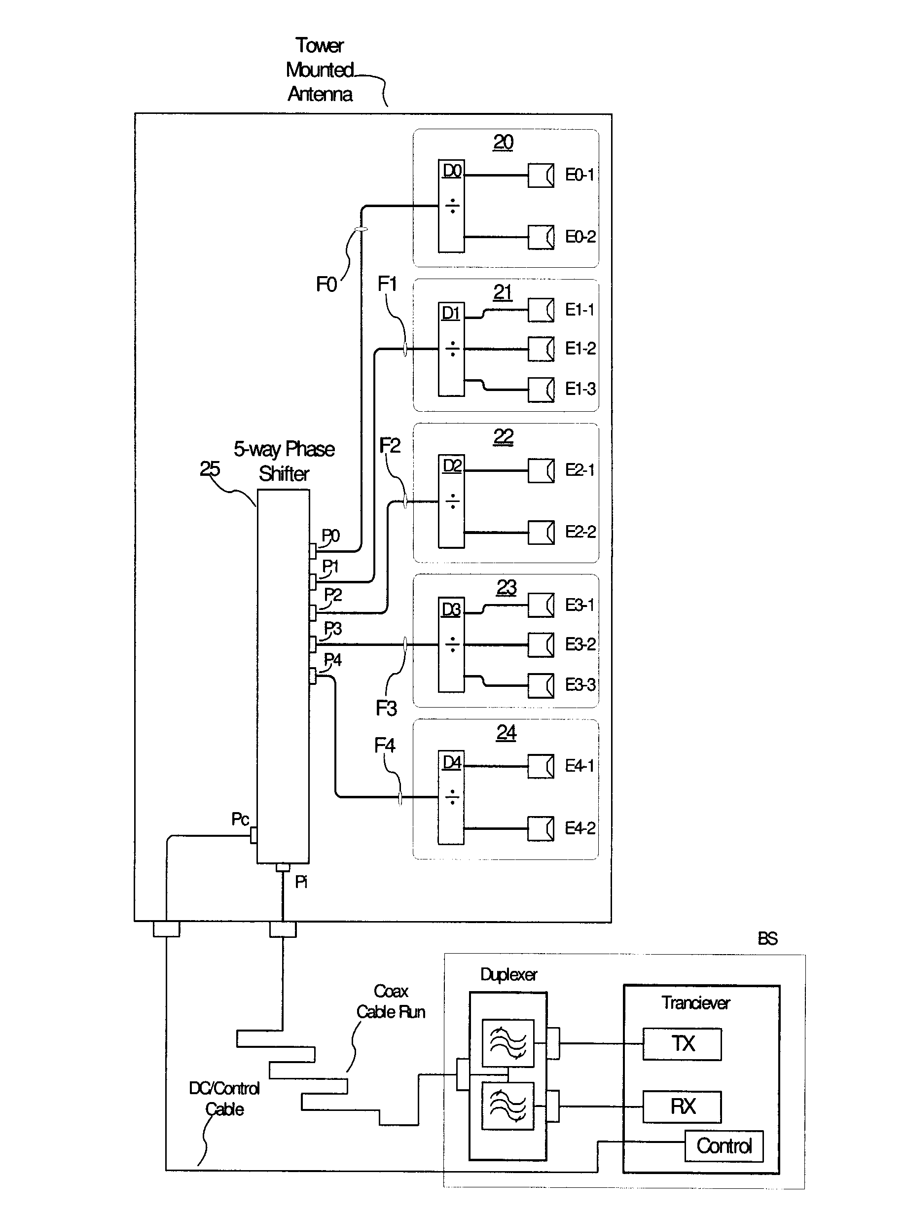
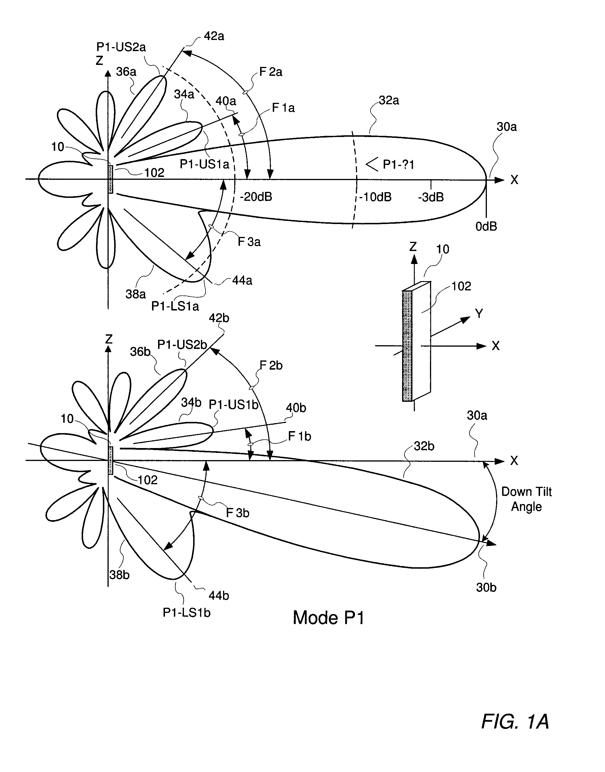
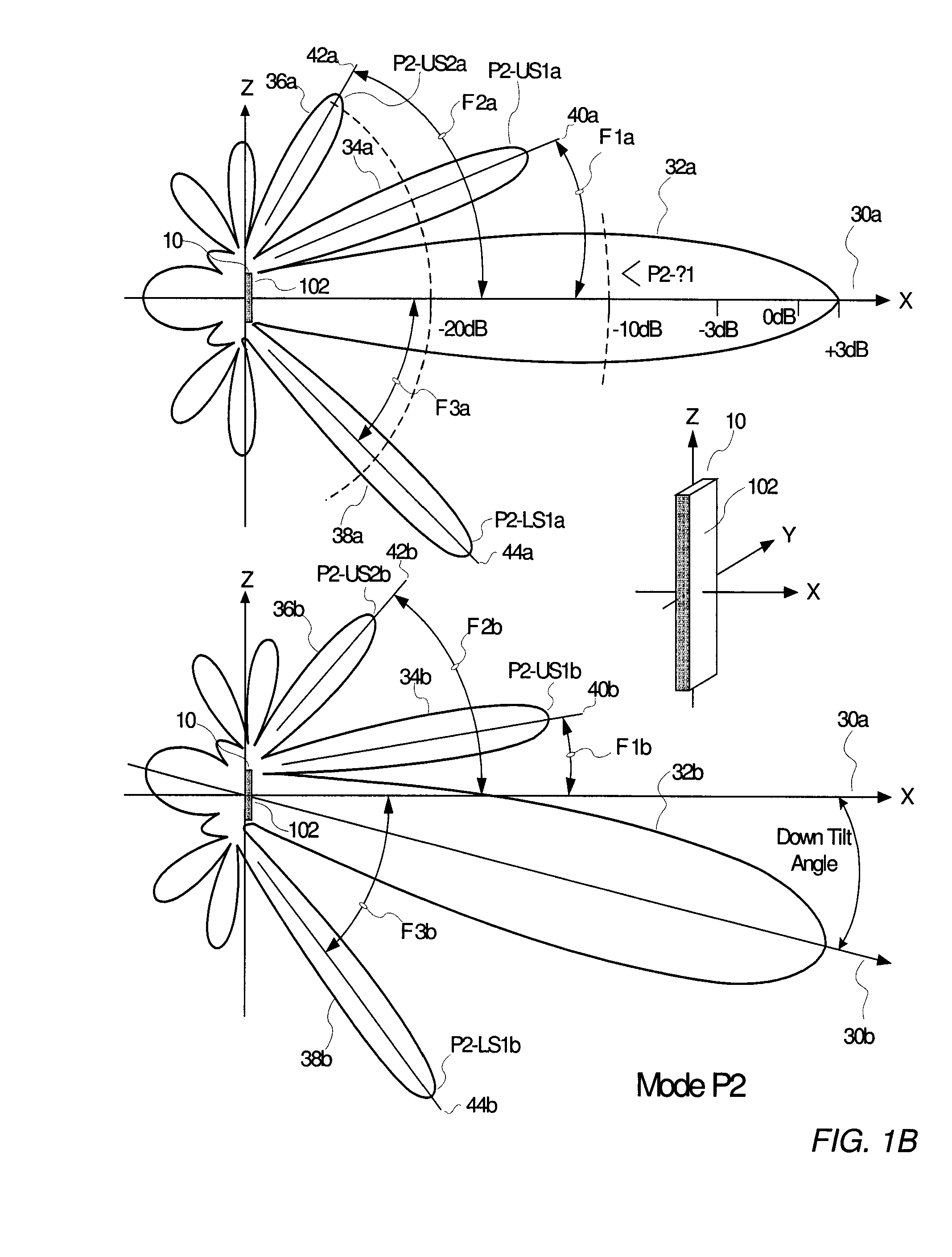
[0038]Reference will be made to the accompanying drawings, which assist in illustrating the various pertinent features of the present invention. Due to multi positioning and use of identical elements in the parallel paths these labels may be referred to without the suffix a or b, since suffix indicates either of the relevant pair of elements is being referred to without distinction. The present invention will now be described primarily in solving aforementioned problems relating to use of predistortion compensated dual elements. It should be expressly understood that the present invention may be applicable in other applications wherein tilt angle and or beamwidth control is required or desired. In this regard, the following description of a predistortion compensated dual polarized antenna array is presented for purposes of illustration and description. Furthermore, the description is not intended to limit the invention to the form disclosed herein. Accordingly, variants and modifica...


PUM


Abstract

An improved communication system and method employing an actively controlled antenna array architecture is disclosed. The array contains a plurality of driven radiating elements that are spatially arranged having a pair of radiating elements fed with an RF signal predistorted so as to provide a controlled variation of the antenna array's elevation radiation pattern. High power amplifier (PA) efficiency is maintained by adaptive predistortion, coupled to each high power PA, while providing beam tilt and side lobe control.

Description

RELATED APPLICATION INFORMATION[0001]The present application claims priority under 35 U.S.C. Section 119(e) to U.S. Provisional Patent Application Ser. No. 61 / 185,137 filed Jun. 8, 2009, the disclosure of which is incorporated herein by reference in its entirety.BACKGROUND OF THE INVENTION[0002]1. Field of the Invention[0003]The present invention relates in general to communication systems and components, and related methods. More particularly, the present invention is directed to actively controlled antenna arrays and methods of actively controlling the elevation radiation pattern of an antenna array.[0004]2. Description of the Prior Art and Related Background Information[0005]Modern wireless antenna array implementations generally include a plurality of radiating elements that may be arranged over a reflector plane defining a radiated (and received) signal beamwidth and elevation plane angle (also known as tilt angle). The elevation plane angle antenna beamwidth can be advantageou...

Claims


Application Information

Patent Timeline
IPC IPC(8): H04B1/40
CPCH01Q1/246H01Q15/0046H01Q3/36H01Q21/08H03F1/3247H03F1/3282H03F3/189H03F3/24H03F2200/192H03F2200/195H03F2200/204H03F2200/207H03F2200/294H03F2200/411H03F2200/451H04B2001/0425H04B1/0475H01Q3/30H03F1/3241
Inventor TEILLET, ANTHONYCARICHNER, SCOTTRABINOVICH, ALEXANDER
Owner INTEL CORP
Learn More