
Scanning microscope and method of imaging a sample

a scanning microscope and sample technology, applied in the direction of discharge tube/lamp details, instruments, optical elements, etc., can solve the problems of loss of resolution along the scanning direction, unfavorable sample assembly, and difficulty in implementing non-uniform speed, so as to increase the throughput of scanning microscope and reduce motion blur

Inactive Publication Date: 2010-12-16
KONINKLIJKE PHILIPS ELECTRONICS NV
View PDF13 Cites 14 Cited by
  • Summary
  • Abstract
  • Description
  • Claims
  • Application Information

AI Technical Summary

Benefits of technology

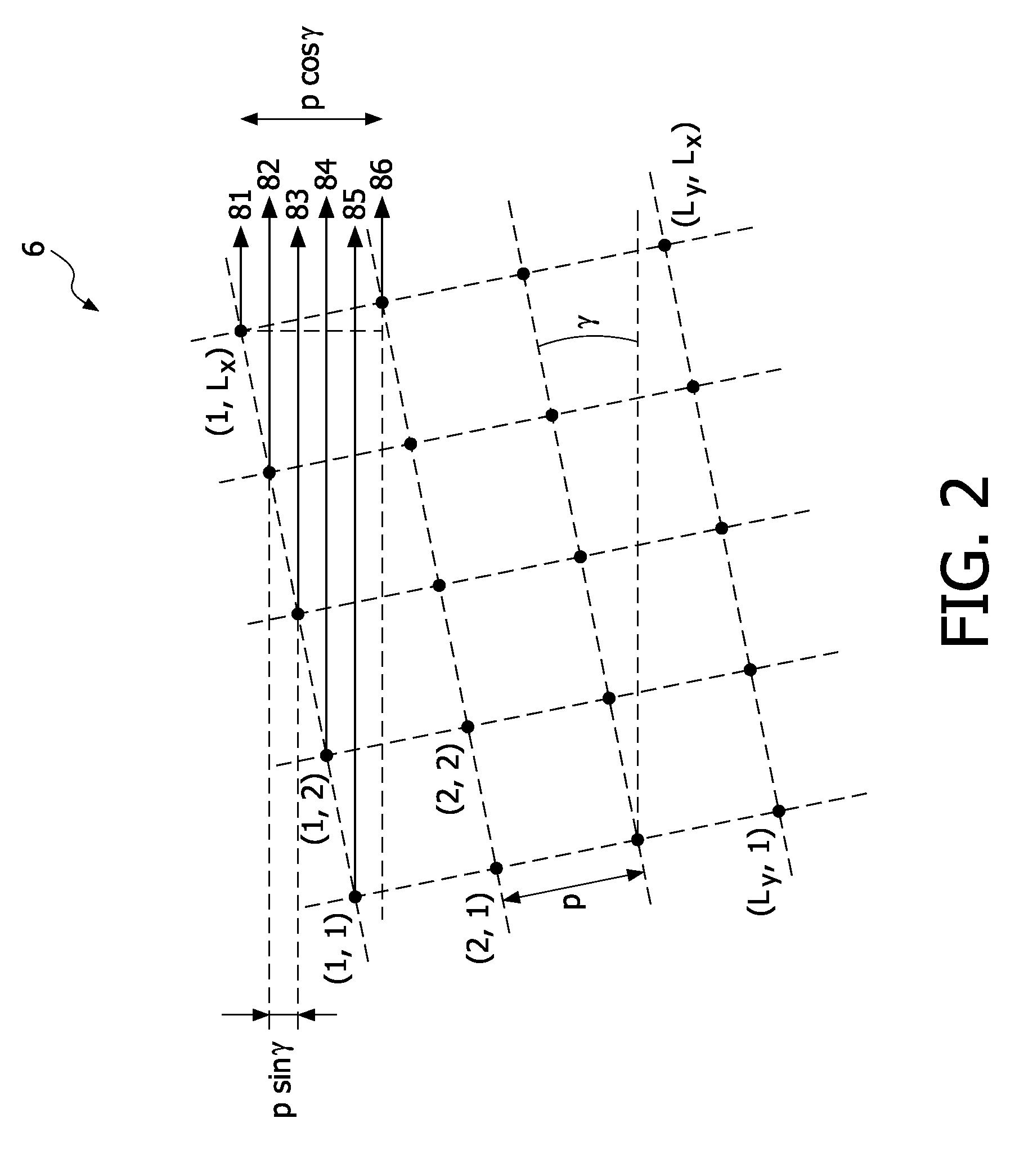
[0024]According to a preferred embodiment of the invention, the step of generating an optical image comprises a step of generating a first light spot and a second light spot within the sample, and the step of displacing the optical image is further characterized in that the first light spot generates a first trace on the photodetector and the second light spot generates a second trace on the photodetector such that the trace of the first light spot and the trace of the second light spot do not cross. Thereby it is avoided that a pixel of the photodetector is exposed to both the first light spot and the second light spot during a single exposure period and it is ensured that the effects from the first light spot and from the second light spot can be analyzed separately.
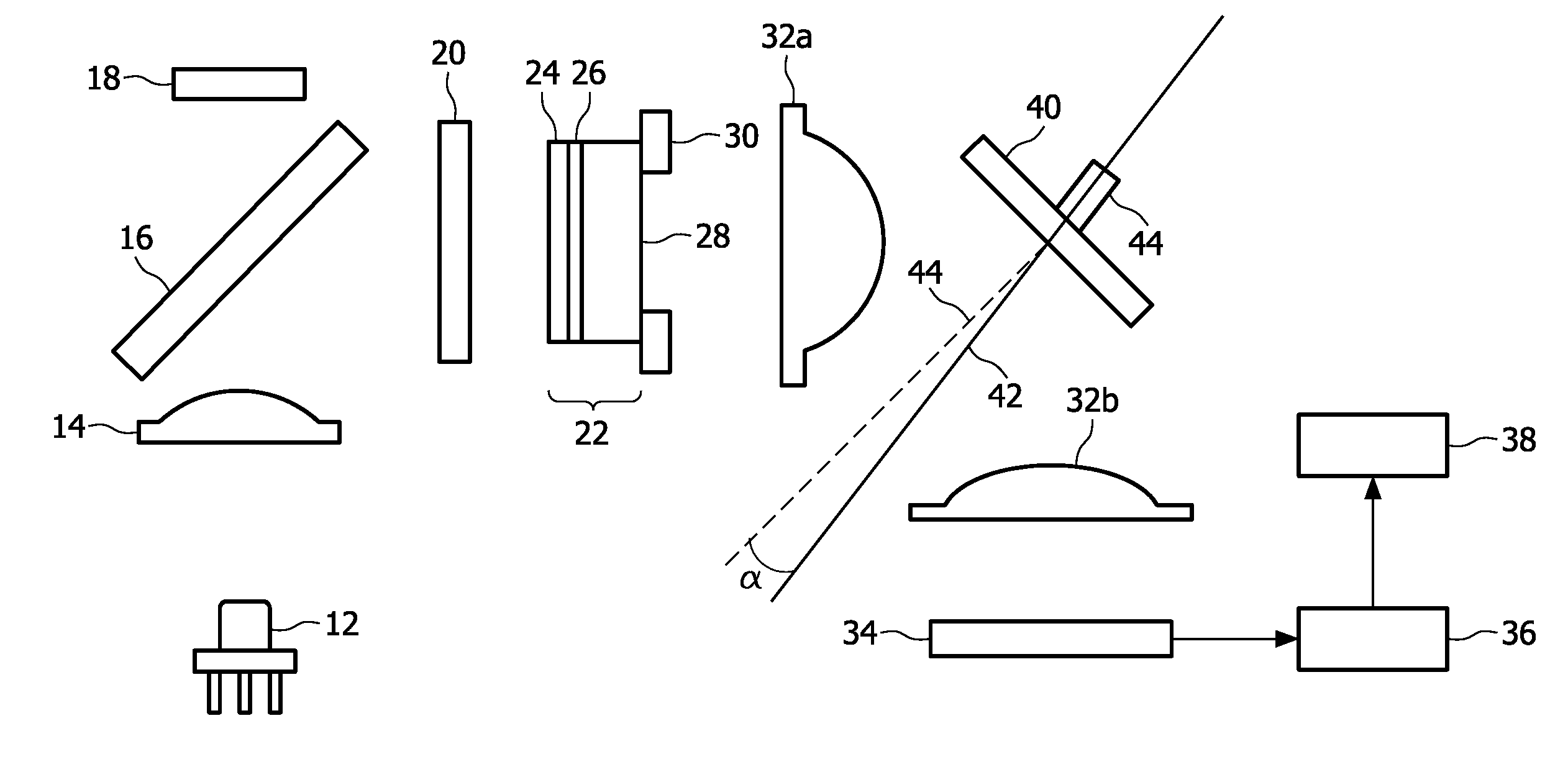
[0025]According to a preferred embodiment of the invention, the step of generating an optical image comprises a step of illuminating the sample using light pulses. Assuming that there are N pulses in the exposure phase, these N pulses give rise to N images on the image sensor that are spatially separated, thus increasing the throughput of the scanning microscope by a factor N. Also, compared to a continuous illumination of the sample, motion blur is reduced, provided the duration of each pulse is short compared to the duration of the exposure phase. Furthermore, the intensity of each light pulse can be sufficiently high to avoid underexposure of the photodetector. In fact underexposure could be a problem in the present method when the energy of a light spot collected during the exposure phase is distributed along a line on the photodetector, rather than being concentrated in a small area.
[0030]Preferably, the image displacement means comprise a rotatable mirror situated on an optical path from the sample to the photodetector. With reference to said optical path, the mirror may be either situated between the sample and an objective, or between the objective and the photodetector, or it may be situated between different components of the objective. The mirror may be plane or curved. Preferably it is plane for ease of manufacturing. However, a curved mirror might be advantageously be used to minimize distortions of the optical image when the optical image is displaced on the photodetector. Preferably, the mirror is rotatable in a periodic manner with a frequency adapted to a frame rate of the photodetector. Preferably the frame rate of the photodetector is an integer multiple of the mirror's rotational frequency. Even more preferably the frame rate of the photodetector is one or two times the mirror's rotational frequency.

Problems solved by technology

A non-uniform speed is difficult to implement and may lead to undesired vibrations of the sample assembly.
Otherwise motion blur on the photodetector would provoke a loss in resolution along the scanning direction.
However, these measures require additional electronic control means and do not solve the trade-off between throughput and resolution.

Method used


Image

  • Scanning microscope and method of imaging a sample
  • Scanning microscope and method of imaging a sample
  • Scanning microscope and method of imaging a sample

Examples


Embodiment Construction

[0043]In the drawings, similar or analogous features appearing in different figures are designated using the same reference numerals and are not necessarily described more than once.

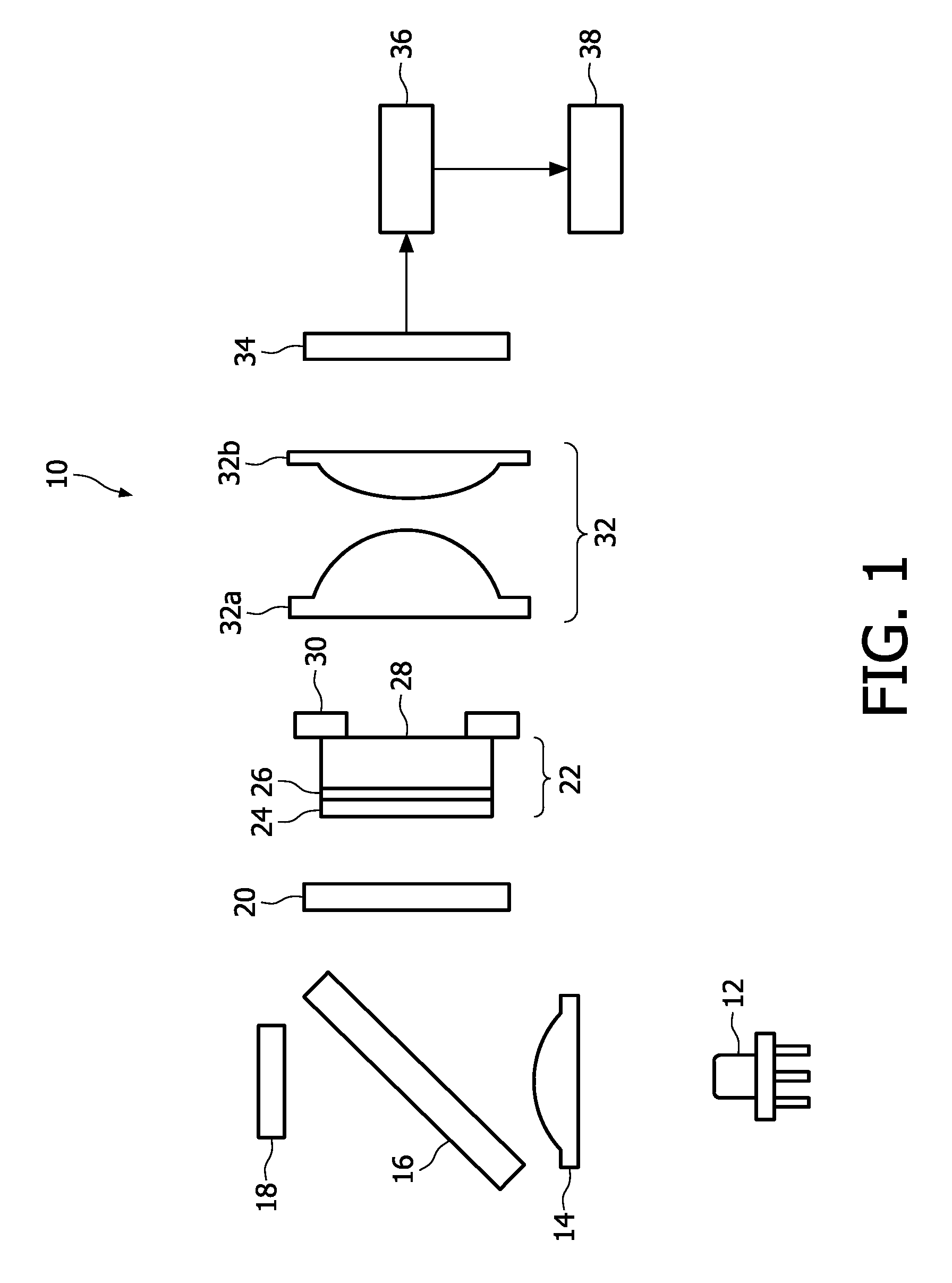
[0044]FIG. 1 schematically illustrates a prior art multispot scanning microscope. The microscope comprises a laser 12, a collimator lens 14, a beam splitter 16, a forward-sense photodetector 18, a spot generator 20, a sample assembly 22, a scan stage 30, imaging optics 32, a pixelated photodetector 34, a video processing integrated circuit (IC) 36, and a personal computer (PC) 38. The sample assembly 22 is composed of a cover slip 24, a sample layer 26, and a microscope slide 28. The sample assembly 22 is placed on the scan stage 30 coupled to an electric motor (not shown). The imaging optics 32 is composed of a first objective lens 32a and a second lens 32b for making the optical image. The objective lenses 32a and 32b may be composite objective lenses. The laser 12 emits a light beam that is collimated...


PUM


Abstract

The invention relates to a method of imaging a sample with a scanning microscope and an imaging system for a scanning microscope, comprising the steps of: initiating an exposure phase of a detector (34) by a pulsed laser source (12); generating an optical image of the sample on the detector with a lens system (32); and terminating the exposure phase. According to the invention, the step of generating the optical image comprises a step of displacing the optical image on the detector with an image displacement means (40) between two consecutive laser pulses. The image displacement means comprise a rotatable mirror (40) situated on an optical path from the sample (26) to the detector (34).

Description

FIELD OF THE INVENTION[0001]The invention relates to a method of imaging a sample with a scanning microscope, comprising the steps of:[0002]initiating an exposure phase of a detector;[0003]generating an optical image of the sample on the detector; and[0004]terminating the exposure phase.[0005]The invention also relates to an imaging system for a scanning microscope, the imaging system comprising:[0006]a detector;[0007]a lens system for generating on the detector an optical image of a sample; and[0008]image displacement means for displacing the optical image on the detector during an exposure phase of the detector.[0009]The invention further relates to a scanning microscope comprising an imaging system as specified above.BACKGROUND OF THE INVENTION[0010]Optical scanning microscopy is a well-established technique for providing high resolution images of microscopic samples. According to this technique, one or several distinct, high-intensity light spots are generated in the sample. Sin...

Claims


Application Information

Patent Timeline
Patent Type & Authority Applications(United States)
IPC IPC(8): G02B21/36
CPCG02B21/0032G02B21/0036G02B21/0084
Inventor STALLINGA, SJOERDHULSKEN, BAS
Owner KONINKLIJKE PHILIPS ELECTRONICS NV
Learn More