Spectroscopic detection system and method

a detection system and optical absorption spectroscopy technology, applied in the direction of optical radiation measurement, reflective surface testing, instruments, etc., can solve the problems of reducing the detection threshold, reducing the resolution limit of the measurement, and rendering frequency modulation spectroscopy techniques (such as those described by j), so as to reduce the detection threshold and achieve the effect of reducing the detection threshold

Active Publication Date: 2010-12-16
AUSTRALIEN NAT UNIV
View PDF3 Cites 25 Cited by
  • Summary
  • Abstract
  • Description
  • Claims
  • Application Information

AI Technical Summary

Benefits of technology

[0013]Described herein are methods and apparatus for shot noise or near shot noise limited detection performance in a spectroscopy technique using a cavity enhanced amplitude modulated laser absorption spectroscopy (CEAMLAS) technique. Arrangements of the method comprise amplitude modulation (AM) interferometry for absorption measurements while the laser is resonant with the cavity. For optimum performance, the measurements are performed in closed-loop operation with active impedance matching of a resonator cavity and frequency locking between the laser and cavity, to ensure a large dynamic range with optimum sensitivity limit, while facilitating a measurement which is immune to the laser intensity noise.

Problems solved by technology

The fundamental challenge is to attain ever lower detection thresholds.
Shot noise on the measurement beam sets the ultimate resolution limit to which this measurement can be made.
With conventional laser modulation technology, this absorption continuum appears as a broadband loss to the spectral components of the frequency modulated laser, which renders frequency modulation spectroscopy techniques (such as those described by J. Ye et. al. referenced above) ineffective.
However, this technique typically yields poor sensitivity due to limited optical duty cycle and large effective noise bandwidth.

Method used


Image

  • Spectroscopic detection system and method
  • Spectroscopic detection system and method
  • Spectroscopic detection system and method

Examples


Embodiment Construction

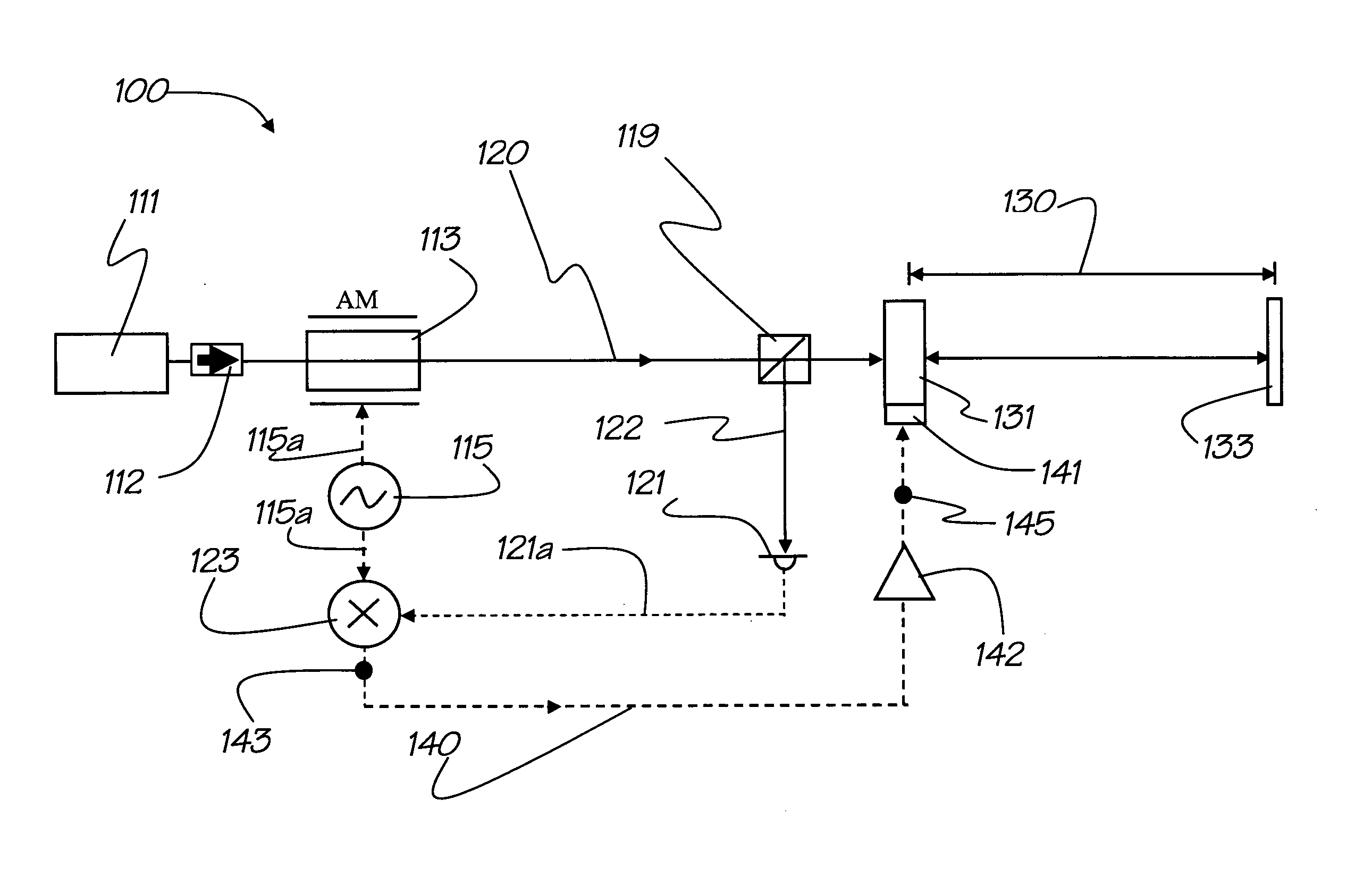
[0059]Described herein is a method and associated apparatus for optical spectroscopy using a cavity enhanced amplitude modulated detection method for shot noise or near shot noise limited detection thresholds. In general terms, an amplitude modulated laser beam with a carrier frequency ωo is held on resonance with an optical resonator cavity containing a loss mechanism and the reflected amplitude modulated light from the resonator cavity is used to determine the magnitude of the loss mechanism in the cavity at the carrier frequency ωo. The methods and apparatus for achieving this are described below and it will be seen by examples that the disclosed method is capable of providing shot noise limited detection of the loss in the resonator cavity.

[0060]In the absence of excess technical laser intensity noise, the fundamental sensitivity limit for a typical laser spectroscopy measurement technique and system is given by the shot-noise-limited relative intensity noise (RINshot) of the me...


PUM

PropertyMeasurementUnit
reflectivityaaaaaaaaaa
frequency modulation (aaaaaaaaaa

Abstract

A system and method for spectroscopic detection of a loss in a resonator cavity. The system comprises: a tunable laser source for generating a laser beam; a frequency locking system for either locking the frequency of the laser beam to a resonance of the resonator cavity or locking the length of the cavity to the frequency of the laser beam; a first modulation element for modulating the laser beam at a first modulation frequency to generate a modulated laser beam; an input coupler adapted for directing the modulated laser beam into the resonator cavity; a first directing element for directing a first portion of light reflected from the input coupler to a first photodetector to generate a first detected signal; and a first demodulator capable of demodulating the first modulation signal from the first detected signal to generate a first error signal which is a function of the loss in the resonator cavity.

Description

TECHNICAL FIELD[0001]The present invention relates to methods and apparatus for optical absorption spectroscopy and in particular to shot nose limited optical absorption spectroscopy methods and apparatus.[0002]The invention has been developed primarily for use as a method and associated apparatus for optical spectroscopy using a cavity enhanced amplitude modulated detection method for shot noise limited detection thresholds and will be described hereinafter with reference to this application. However, it will be appreciated that the invention is not limited to this particular field of use.BACKGROUND OF THE INVENTION[0003]Any discussion of the background art throughout the specification should in no way be considered as an admission that such background art is prior art, nor that such background art is widely known or forms part of the common general knowledge in the field.[0004]Optical absorption spectroscopy is an active branch of research which finds important applications in bio...

Claims


Application Information

Patent Timeline
Patent Type & Authority Applications(United States)
IPC IPC(8): G01N21/00
CPCG01J3/433G01M11/005G01N21/39G01N2021/391H01S3/1392H01S3/1398
Inventor CHOW, JONG HANNGRAY, MALCOLM BRUCELITTLER, IAN CHARLES MURRAYMCCLELLAND, DAVID ERNEST
Owner AUSTRALIEN NAT UNIV
Why Eureka
Try Eureka