Fuel cell system

Inactive Publication Date: 2010-12-16
TOYOTA JIDOSHA KK
View PDF5 Cites 18 Cited by
  • Summary
  • Abstract
  • Description
  • Claims
  • Application Information

AI Technical Summary

Benefits of technology

[0007]Thus, it is an object of the present invention to suppress erroneous integration of an actual flow quantity and a target value of a reactive gas when a fluctuation in load of a fuel cell is large, thereby reducing an overshoot of a reactive gas supply flow amount.
[0009]Changing the update arithmetic operation of the integral term based on the deviation of the actual flow quantity and the target value of the reactive gas supplied to the fuel cell enables suppressing erroneous integration of the deviation of the actual flow amount and the target value of the reactive gas when a fluctuation in load of the fuel cell is large, thereby suppressing an overshoot of a reactive gas supply flow quantity.
[0011]When the deviation of the actual flow quantity and the target value of the fuel gas is equal to or above the predetermined threshold value, since a fluctuation in load of the fuel cell is increased, inhibiting erroneous integration of the deviation of the actual flow quantity and the target value of the fuel gas in such a case enables suppressing an overshoot of the fuel gas supply flow quantity.

Problems solved by technology

In a system that performs feedback control with respect to gas jetting from an injector based on a proportional-plus-integral action, when a deviation of the injector secondary pressure and the injector secondary pressure instruction value is regarded as a steady-state deviation to carry out an update arithmetic operation of an integral term in such a transient state, a value of the integral term is increased beyond necessity, and hence there arises an inconvenience that the injector secondary pressure is overshot when the injector secondary pressure instruction value is stabilized at a fixed value.
Such a problem is an issue that is common to systems each of which performs feedback control with respect to supply of a reactive gas to a fuel cell from a reactive gas supplying apparatus (e.g., an air compressor or a hydrogen circulating pump) based on a proportional-plus-integral action.

Method used


Image

  • Fuel cell system
  • Fuel cell system
  • Fuel cell system

Examples


Embodiment Construction

[0020]An embodiment according to the present invention will now be described hereinafter with reference to the respective drawings.

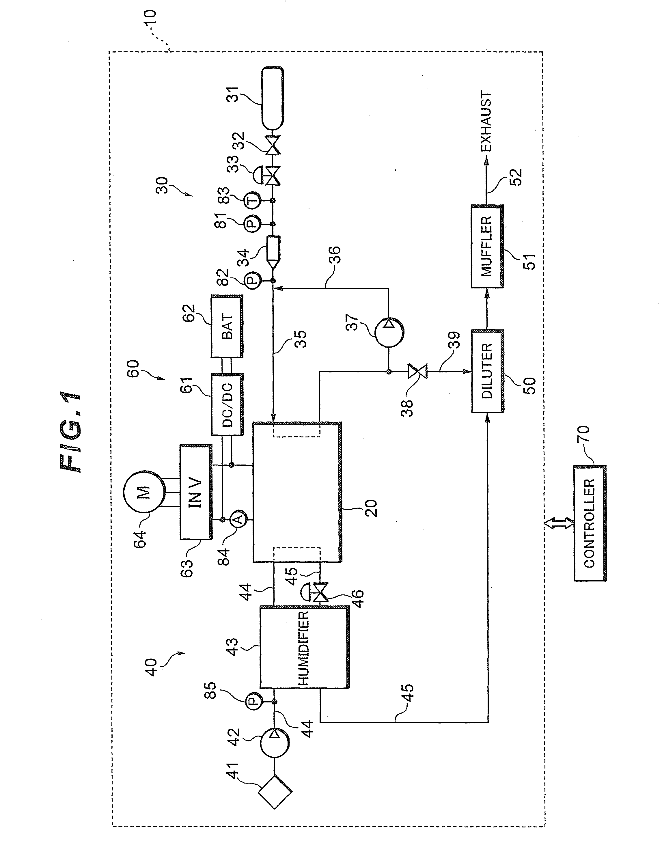
[0021]FIG. 1 shows a system configuration of a fuel cell system 10 that functions as an in-vehicle power supply system for a flue cell vehicle.

[0022]The fuel cell system 10 includes a fuel battery stack 20 that generates electric power upon receiving supply of a reactive gas (an oxidizing gas and a fuel gas), a fuel gas piping system 30 that supplies a hydrogen gas as the fuel gas to the fuel cell stack 20, an oxidizing gas piping system 40 that supplies air as an oxidizing gas to the fuel cell stack 20, a power system 60 that controls charge / discharge of electric power, and a controller 70 that performs overall control of the entire system.

[0023]The fuel cell stack 20 is, e.g., a polyelectrolyte type cell stack obtained by laminating many cells in series. The cell has a cathode pole on one surface of an electrolytic film formed of an ion-exchange membra...


PUM


Abstract

A fuel cell system performs feedback control with respect to a reactive gas supplying apparatus based on a proportional obtained by multiplying a deviation of an actual flow quantity from a target value of a reactive gas supplied to the fuel cell from the reactive gas supplying apparatus by a proportional gain and an integral term obtained by multiplying the deviation by an integration gain to perform time integration in such a manner that the actual flow quantity coincides with the target value, and changes an update arithmetic operation of the integral term in accordance with a value of the deviation.

Description

TECHNICAL FIELD[0001]The present invention relates to a fuel cell system including a reactive gas supplying apparatus that supplies a reactive gas to a fuel cell.BACKGROUND ART[0002]In recent years, as a part of efforts to environmental issues, development of a low-emission vehicle has been advanced, and there is a fuel cell vehicle using a fuel cell as an in-vehicle power supply as one of such vehicles. A fuel cell system is an energy conversion system which supplies a reactive gas to a membrane-electrode assembly having an anode pole arranged on one surface of an electrolytic film and a cathode pole arranged on the other surface to bring about an electrochemical reaction, thereby converting chemical energy into electrical energy. Among others, a polyelectrolyte type fuel cell system that uses a solid polymer film as an electrolyte can be reduced-in size at a low cost and has a high power density, and hence an application as an in-vehicle power source is expected.[0003]As means for...

Claims


Application Information

Patent Timeline
IPC IPC(8): H01M8/04
CPCH01M8/04201H01M8/04328H01M8/04388H01M8/04395H01M8/04559H01M8/04589H01M8/04753H01M8/04761H01M8/04992Y02E60/50
Inventor ISHIKAWA, NORIMASAYUMIYA, HIROYUKIISHIGAKI, KATSUKI
Owner TOYOTA JIDOSHA KK
Why Eureka
Try Eureka