
Magnetic resonance imaging using hyperpolarization of liquids or solids by light with orbital angular momentum

Inactive Publication Date: 2010-12-16
KONINKLIJKE PHILIPS ELECTRONICS NV
View PDF16 Cites 21 Cited by
  • Summary
  • Abstract
  • Description
  • Claims
  • Application Information

AI Technical Summary

Benefits of technology

[0012]One advantage is that blood can be more effectively imaged using nuclear resonance without aid of chemical contrast agents.
[0013]Another advantage lies in improved access to the subject.
[0014]Another advantage resides in lower cost.
[0015]Anoth

Problems solved by technology

This approach, however, only enables MRI scanners to polarize a small fraction of the water protons; for example, a 1.5 Tesla magnetic field, at room temperature, will polarize only about 3 protons out of one million.
This inefficiency places limitations on the resolution, sensitivity, and dynamic contrast range of MRI.
A drawback is that the typical setup requires large magnets, gradient field coils, and radio frequency (RF) coils, adding to the bulk, complexity, and cost of the system.
Drawbacks include the aforementioned problem of a small imaging region and only polarizing a few protons per million, but this is in part balanced by the proximity to the resonating protons.
These methods, however, have only been shown to be suitable for hyperpolarizing low density noble gases, such as Xenon or Helium, under controlled laboratory conditions.
Existing methods have not contemplated hyperpolarization of liquids or solids which would enable the standard MR imaging signal associated with blood and biological tissue to be enhanced.

Method used


Image

  • Magnetic resonance imaging using hyperpolarization of liquids or solids by light with orbital angular momentum
  • Magnetic resonance imaging using hyperpolarization of liquids or solids by light with orbital angular momentum
  • Magnetic resonance imaging using hyperpolarization of liquids or solids by light with orbital angular momentum

Examples


Embodiment Construction

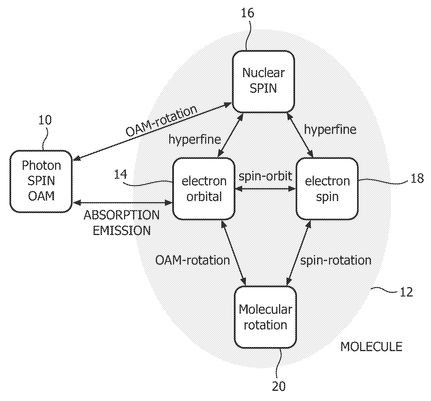
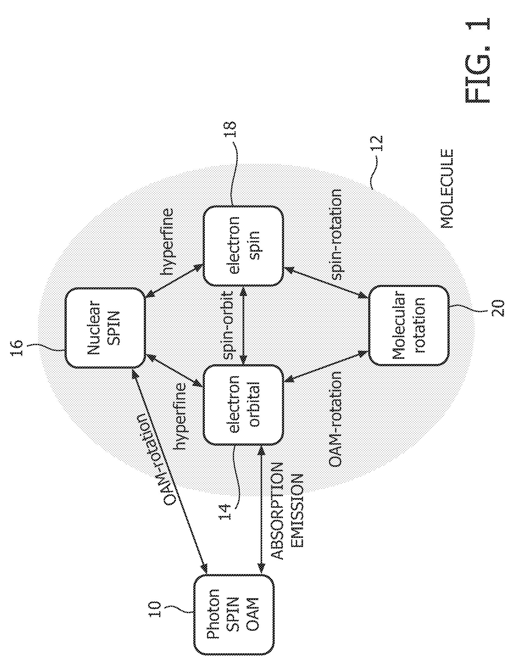
[0028]Orbital angular momentum (OAM) is an intrinsic property of all azimuthal phase-bearing light, independent of the choice of axis about which the OAM is defined. When interacting with an electronically distinct and isolated system, such as a free atom or molecule, OAM can be transferred from the light to the matter.

[0029]Various experiments have used the interaction of OAM-endowed light with matter, for example, optical tweezers, high-throughput optical communication channels, optical encryption techniques, optical cooling (Bose-Einstein condensates), entanglement of photons with OAM, and entanglement of molecule quantum numbers with interacting photons' OAM. Because angular momentum is a conserved quantity, the OAM of absorbed photons is transferred in whole to interacting molecules. As a result, affected electron states reach saturated spin states, angular momentum of the molecule about its own center of mass is increased and oriented along the propagation axis of the incident...


PUM


Abstract

In magnetic resonance imaging (MRI), selected magnetic dipoles in a subject are aligned with a main magnetic field for later manipulation, and signals received after such manipulations are used to create image representations of the subject. One drawback is that even powerful magnetic fields can only align a very small percentage of dipoles in the region of the field. Electromagnetic radiation endowed with orbital angular momentum (OAM) aligns dipoles along the direction of travel of the radiation, but at a much higher percentage; as high as 100% of the dipoles in the region can be aligned. Resultantly, resonance signals emanating from the region are several orders of magnitude stronger than signals emanated using traditional MRI techniques. All electromagnetic radiation, including visible light can be endowed with OAM and used to hyperpolarize a region of interest.

Description

FIELD OF THE INVENTION[0001]The present application relates to the diagnostic imaging arts. It finds particular application in magnetic resonance imaging of regions near the surface of a subject's skin or accessible with a probe or catheter, and will be described with particular reference thereto. It is to be appreciated, however, that it is also applicable to other regions or areas, contrast enhanced imaging, spectroscopy and is not limited to the aforementioned applications.BACKGROUND OF THE INVENTION[0002]Conventional magnetic resonance imaging (MRI) uses powerful magnetic fields to align, that is, polarize the spin vector of protons, particularly protons inside the hydrogen nuclei in water molecules. Using RF excitation pulses, the system knocks the spin vectors out of alignment, and as they re-align, they produce a resonance signal that is used for imaging. This approach, however, only enables MRI scanners to polarize a small fraction of the water protons; for example, a 1.5 Te...

Claims


Application Information

Patent Timeline
IPC IPC(8): A61B5/055G02B5/32
CPCG01N24/08G01R33/282G01R33/285G02B27/46G02B27/0037G02B27/4244G02B27/425G02B5/32
Inventor ELGORT, DANIEL R.ALBU, LUCIAN REMUS
Owner KONINKLIJKE PHILIPS ELECTRONICS NV
Learn More