Biopsy guidance by electromagnetic tracking and photonic needle

a technology of electromagnetic tracking and photonic needles, applied in the direction of catheters, diagnostics using spectroscopy, applications, etc., can solve the problems of limited imaging system resolution, insufficient tissue characterization, and insufficient tissue characterization, so as to achieve reliable tissue characterization

Active Publication Date: 2010-12-16
KONINKLJIJKE PHILIPS NV
View PDF35 Cites 39 Cited by
  • Summary
  • Abstract
  • Description
  • Claims
  • Application Information

AI Technical Summary

Benefits of technology

[0026]Another aspect of the invention is that in translating the measured optical data into a tissue type can be difficult when no information about the surrounding morphology is known. Hence the decision making of the tissue characterization improves having the morphology information coming from the non-invasive imaging system as input. Hence preferably first the optical data is registered to the non-invasive imaging data, then the optical information together with the morphology information around the needle coming from the non-invasive imaging modality is used in translating the measured optical data into a tissue type in front of or near the needle. For instance when the needle is in soft tissue the optical information can be affected whether a bone structure is close by or not. Taking this into account a more reliable tissue characterization is possible.

Problems solved by technology

Although helpful, these methods of guidance are far from optimal.
There are problems directly related to the biopsy:
The resolution of the imaging system is limited and, furthermore, these imaging modalities cannot in most cases discriminate normal and neoplastic tissue and further differentiate between benign and malignant tissue.
As a result of that, there is a high level of uncertainty whether an appropriate tissue specimen is taken.
In addition to that, the biopsies are often taken blindly, with limited feedback of where the needle is relative to the target tumor, which leads to an additional uncertainty whether the lesion has been hit by the needle.
However the accuracy of the method is limited to a few millimeters.
As a result for small sized suspicious tissue volumes there is a certain chance of taking the biopsy at the wrong place.
A further limitation is that even if one could guide the biopsy needle to the exact location corresponding to the pre-recorded image, one is never sure that this is the exact location due to the compressibility of the tissue.
Due to the force of the biopsy needle on the tissue during advancement, the tissue may become deformed.
The surgical approach is confounded by the fact that the surgeons typically use only their eyes and hands (palpation) to find the tumor and have to rely on the information of pre-recorded images.
These pre-recorded images provide information on the position of the tumor but do not always clearly show the tumor boundaries.
Again guiding the localization wire to the correct position is difficult.
It is particularly difficult to find the boundaries of the tumor, in fact it is virtually impossible.
Although removing an additional amount of tissue around the tumor will indeed lead in most cases to complete removal, the surgeon is never sure.
One could of course increase the amount of tissue to be removed but this in several cases difficult.
It is important to note that when resection is not complete, the surgeon has, in fact, cut through the tumor and may cause further dissemination of the tumor.
The same drawbacks apply for these interventions where it is difficult to guide the biopsy device to the correct location.
The current way of working to take a biopsy has some drawbacks, including:difficult to guide the biopsy needle to a centre of the tissue to be investigated;difficult to delineate the tumor boundaries (shape and size of tumor); andtaking specimen out of the body for the histological analysis may cause further dissemination of the tumor.

Method used


Image

  • Biopsy guidance by electromagnetic tracking and photonic needle
  • Biopsy guidance by electromagnetic tracking and photonic needle
  • Biopsy guidance by electromagnetic tracking and photonic needle

Examples


Embodiment Construction

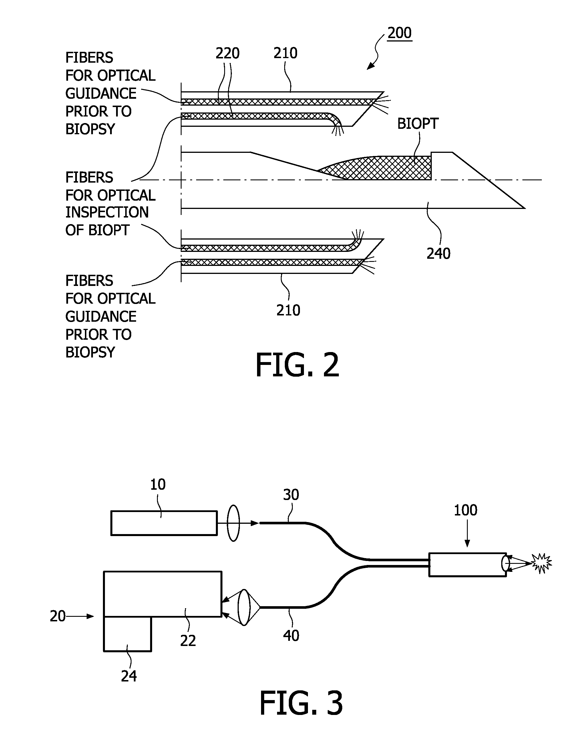
[0041]The first embodiment is based on a needle navigation based needle guidance system as described in U.S. Pat. No. 6,785,571. Furthermore, the shaft 210 of the biopsy device 200 contains a fiber 220 or fiber bundle (see FIG. 2). Further, the shaft 210 is adapted to accommodate a needle 240 for taking a biopt. Preferably, the fiber bundle 220 is located in the shaft 210 such that the respective ends of the fibers are located in the tip portion of the biopsy device. In other words, some of the fibers might end in the front surface of the biopsy device, and / or some of the fibers might end in the vicinity of the front surface at the side surface or wall surface of the biopsy device. Furthermore, there could be some fiber ends orientated in the direction to a biopt harvested by the biopsy device, and some other fiber ends orientated in the direction to the front or the side of the biopsy device, for optical guidance prior to biopsy.

[0042]It is noted, that any fiber might be used to em...


PUM


Abstract

A system for providing integrated guidance for positioning a needle in a body has two levels of guidance: a coarse guidance and a fine guidance. The system comprises a non-invasive tracking system (400) for tracing the biopsy device (100) in the body, for providing the coarse guidance. Furthermore, the system comprises an optical detector (101′, 102′, 103′) mounted on the needle (100) for obtaining optical information discriminating tissue in the body, for providing the fine guidance.

Description

FIELD OF THE INVENTION[0001]The present invention relates to a system for integrated guidance for positioning a biopsy device in a body, to a biopsy device and to a method for positioning a biopsy device.BACKGROUND OF THE INVENTION[0002]For correct diagnosis of various cancer diseases biopsies are taken. This can either be done via a lumen of an endoscope or via needle and catheter biopsies. An example of a needle biopsy is shown in FIG. 1, where a biopsy is taken from the prostate via the rectum. In order to find the correct position to take the biopsy, various imaging modalities are used such as X-ray, CT, MRI and ultrasound. In case of prostate cancer in most cases the biopsy is guided by ultrasound (see FIG. 1). Although helpful, these methods of guidance are far from optimal.[0003]There are problems directly related to the biopsy:[0004]The resolution of the imaging system is limited and, furthermore, these imaging modalities cannot in most cases discriminate normal and neoplast...

Claims


Application Information

Patent Timeline
Patent Type & Authority Applications(United States)
IPC IPC(8): A61B5/05A61B10/02
CPCA61B5/0066A61B5/0075A61B5/0084A61B5/6848A61B10/0275A61B17/3403A61B2019/5276A61B19/5244A61B2017/00061A61B2017/00066A61B2019/5206A61B2019/5251A61B17/3421A61B10/04A61B2576/00A61B34/20A61B2034/2051A61B2090/306A61B2090/378
Inventor HENDRIKS, BERNARDUS HENDRIKUS WILHELMUSSHECHTER, GUYBABIC, DRAZENKOCROOIJMANS, WIM
Owner KONINKLJIJKE PHILIPS NV
Why Eureka
Try Eureka